
Self-raising magazine loader

a self-raising, magazine-loading technology, applied in the direction of ammunition loading, weapon components, weapons, etc., can solve the problems of slowing down the loading process, wasting time, and tedious practice if done with bare fingers, so as to reduce the pain and increase the load

Active Publication Date: 2015-12-15
MAGLULA
View PDF27 Cites 70 Cited by
  • Summary
  • Abstract
  • Description
  • Claims
  • Application Information

AI Technical Summary

Benefits of technology

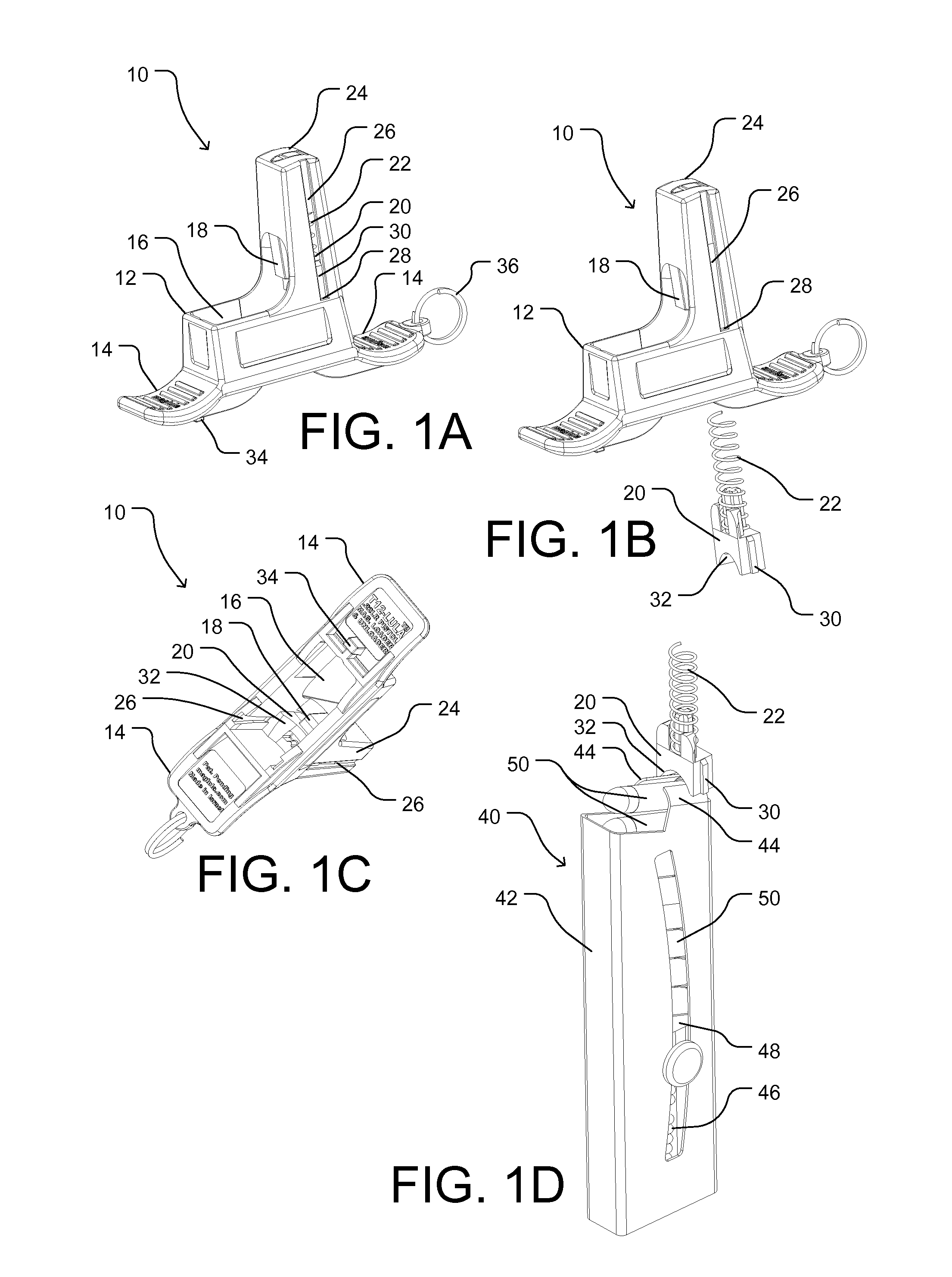
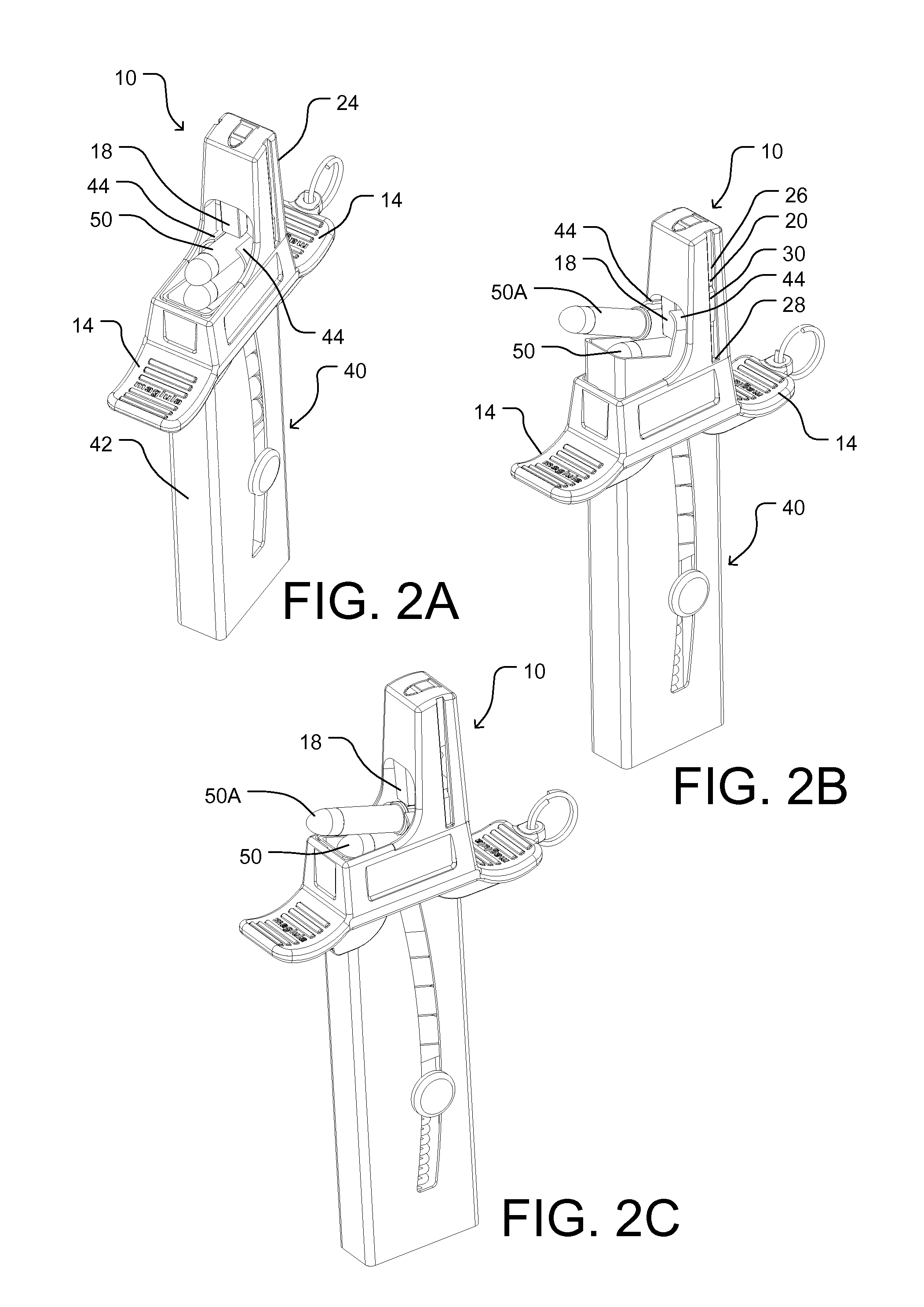
The present tool is a tool for loading loose rounds into a firearm magazine. It comprises a body with finger rests and a plunger tooth, a magazine pusher, and a spring. The pusher can be positioned adjacent the plunger and the spring is located between the pusher and the inner topmost part of the body. The dimensions of the rectangular opening are slightly larger than the cross-sectional dimensions of the magazine group for which the loader is made. To use the tool, an eye is positioned on the magazine and the loader is forced down so its plunger pushes the topmost round down into the magazine. The pusher is then raised to clear the plunger and the round is forced further in to its final position in the magazine. The tool simplifies the process of loading small caliber rounds into a firearm magazine.

Problems solved by technology

Loading magazines is relatively time-consuming, tedious, and painful practice if done with bare fingers.
Pain accumulates and intensifies as more rounds are loaded against the increasing spring pressure, thus slowing the loading process.
When a user loads a plurality of magazines, much time is required, shortening reposing, training, or combat time.
In combat circumstances, slow reloading can be life-threatening.
All the above loaders are not comfortable to use and are cumbersome, slow, and require several operator steps to load a round.
Newman shows a large and cumbersome spring-loaded lever-operated loader comprising many parts.
Williams also shows a spring-loaded thumb-operated loader with an odd and unfriendly construction.
While it may facilitate loading, the necessity of attachment, sliding a new round in, and detachment makes its use inefficient, tedious, and awkward.
It further lacks a structure which is comfortable for repeated use against the magazine's spring pressure, and is generally flimsy and delicate to use under field conditions.

Method used


Image

  • Self-raising magazine loader
  • Self-raising magazine loader
  • Self-raising magazine loader

Examples


second embodiment

Operation—Second Embodiment

FIGS. 3A-3D

[0072]The operation of loader 60 is similar to that of loader 10. The loader is self-raising once the user releases force on the loader. This eliminates the need to raise the loader up to clear tooth 68 from between lips 94 of the magazine. Since the loader body is relatively large, the user has a good grip on the loader for comfortable loading, using no finger rests.

third embodiment

FIGS. 4A-4D—Pusher Is Spring

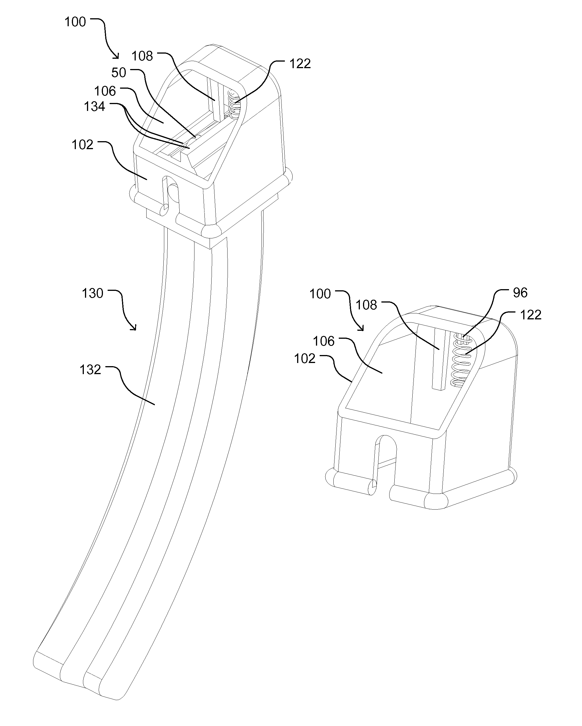
[0073]FIGS. 4A to 4D are perspective views of a second alternative loader 100 comprising only two parts—a body and spring; no magazine pusher element is provided. Loader 100 is seen from various angles, with FIGS. 4A and 4B showing the loader from above and right and FIGS. 4C and 4D from below and front. The loader is shown, as an example, for loading high-capacity Ruger 10 / 22 .22LR style magazines 130 having a body 132 and feed lips 134. Loader 100 is slightly different from loaders 10 and 60 in that its spring serves to push the magazine directly. Thus the loader has two main parts, a body with a rounds tooth or plunger and a spring. The spring shown is a compression spring. The method of loading and principles of operation are similar. Loader 100 has a body 102 with a chamber 106 and a rounds plunger tooth 108. The loader has no pusher element (20 or 70 in FIGS. 1B and 3B). Instead the loader uses only a pusher spring 122 with two ends. The spring's up...


PUM


Abstract

A magazine loader (10) facilitates loading loose rounds into a firearm magazine. The loader comprises a body (12) with finger rests (14), a plunger tooth (18), a pusher element (20), and a spring (22). The body includes an opening (16) to accept the magazine. The tooth pushes down the topmost round (50). The pusher element and the spring push the loader up after each round is partially loaded. To load a round, the loader is fitted on the magazine and forced down so its tooth pushes the topmost round down sufficient to insert a new round, rim first, until it engages the plunger. Then, the user reduces force on the loader to allow the pusher to lift the loader up so that the plunger is cleared from the magazine, whereupon the partially inserted round can be forced rearwardly to its final position in the magazine.

Description

CROSS-REFERENCE TO RELATED APPLICATION[0001]This patent claims priority of our Provisional Patent Application Ser. No. 61 / 826,767, Filed 2013 May 23.BACKGROUNDPrior Art[0002]Small firearms, including pistols, assault rifles, and submachine guns, utilize and fire rounds (also known as cartridges and ammunition). Each round is substantially elongated and comprises a deep cylindrical cuplike case (also known as a shell casing and sometimes also a cartridge), usually of brass, which is filled with an explosive propellant. At its rear or closed end, the case has a rim or flange containing a primer; the front and opposite end of the case is open. A bullet, slug, or head, usually of lead (optionally jacketed) is partially inserted into the open or front end of the case, whereafter the case is crimped onto the bullet.[0003]The rounds are usually held within and fed into the firearm from a magazine, also known as a clip. A detachable magazine has become dominant throughout the world. The ter...

Claims


Application Information

Patent Timeline
Patent Type & Authority Patents(United States)
IPC IPC(8): F41A9/83F41A9/82
CPCF41A9/83
Inventor TAL, RANTAL, GUY
Owner MAGLULA
Learn More