
Identifying mobile station in a cellular wireless communication system

a technology of cellular wireless communication and mobile station, applied in the direction of wireless communication, network data management, electrical equipment, etc., to achieve the effect of improving system performance, reducing drawbacks, and reducing costs

Active Publication Date: 2015-11-24
HUAWEI TECH CO LTD
View PDF5 Cites 10 Cited by
  • Summary
  • Abstract
  • Description
  • Claims
  • Application Information

AI Technical Summary

Benefits of technology

[0022]An object of the present invention is to provide a solution which mitigates or solves the drawbacks and problems of prior art solutions. Another object of the invention is to provide a solution which makes it possible to identify mobile stations in connection with handovers so that radio network parameters can be analysed and / or adjusted so as to improve system performance.
[0029]The present invention provides a novel way of identifying mobile stations in connection with handover in cellular wireless communication systems. Especially, the invention provides means for a network control node receiving a mobile identity indicator to utilise stored mobile station context information for analyzing and / or adjusting radio network parameters. Preferably, mentioned radio network parameters are mobility parameters used in handover procedures. Thereby, system performance, such as handover success rate can be improved.

Problems solved by technology

Too early—a scenario where handover is triggered too early, for example when the UE fails to connect to the target cell or when the UE connects but the radio link fails shortly after the (successful) handover.

Method used


Image

  • Identifying mobile station in a cellular wireless communication system
  • Identifying mobile station in a cellular wireless communication system
  • Identifying mobile station in a cellular wireless communication system

Examples


case i

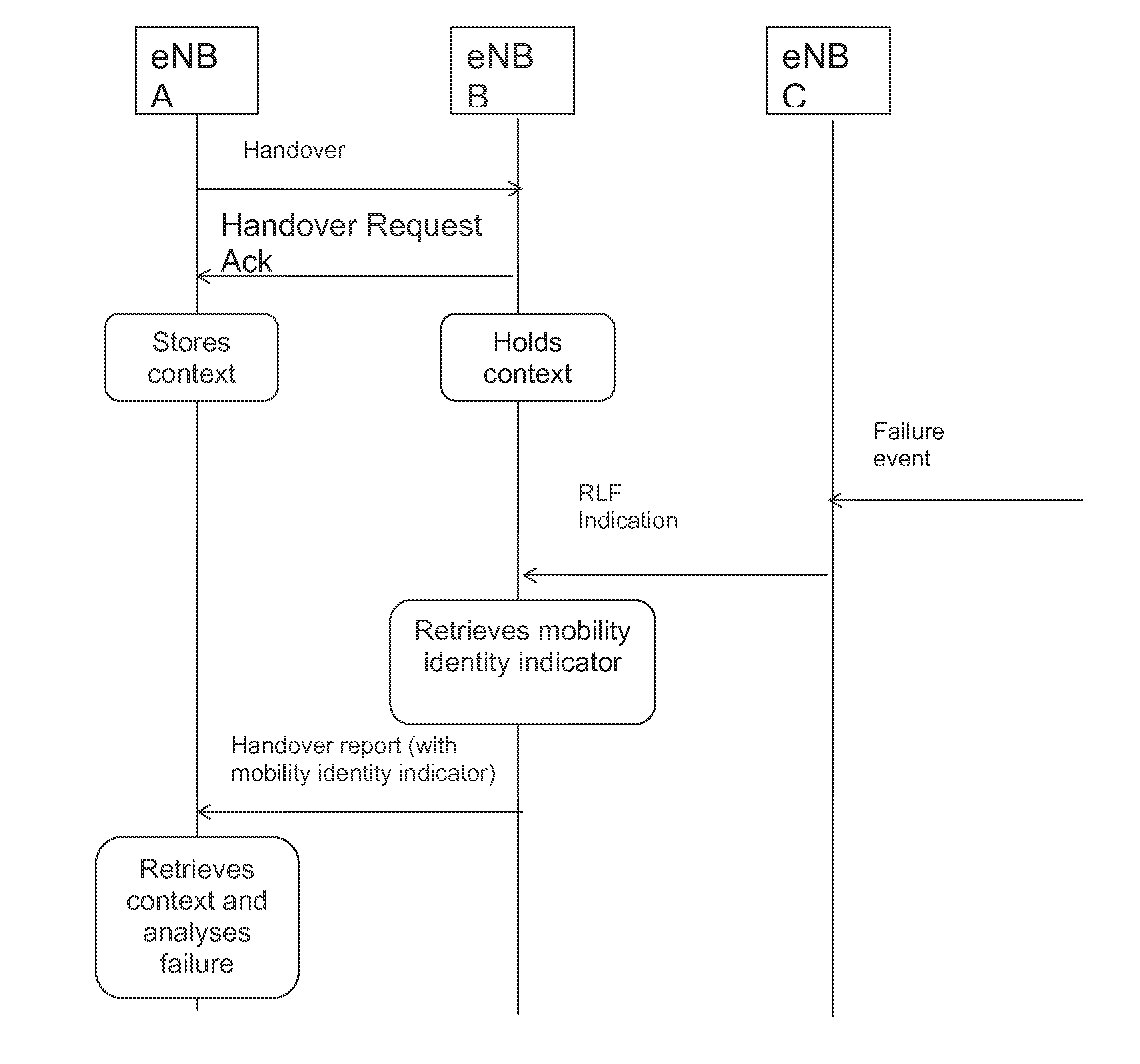
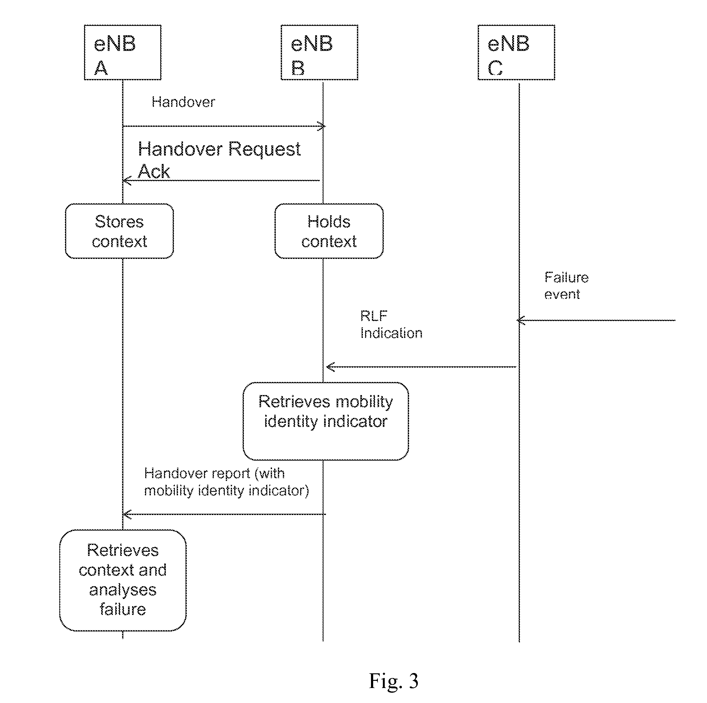
[0058] RLF indication triggered at RRC re-establishment in this case, the UE provides the CRNTI and optionally a shortMAC-I to the eNB C which sends this in an RLF indication message to eNB B. The eNB B retrieves information for this UE, and includes for example the CRNTI used in cell A together with the time the handover from the eNB A to the eNB B occurred (as a timestamp or the elapsed time since this handover occurred) in the Handover Report to eNB A. This provides enough information for the eNB A to retrieve the context of this specific UE.

case ii

[0059] RLF indication triggered at RRC connection setup; adding CRNTI and shortMAC-I to the RLF report)

[0060]Similar to case I above, the UE provides the CRNTI and shortMAC-I used in the eNB B (but carried in the RLF report) to the eNB C which sends this in a RLF Indication message to the eNB B. The eNB B retrieves information for this UE, and includes for example the CRNTI used in cell A together with the time the handover from the eNB A to the eNB B occurred (as a timestamp or the elapsed time since this handover occurred) in the Handover Report to cell A. This provides enough information for the eNB A to retrieve the context of this specific UE.

case iii

[0061] RLF indication triggered at RRC connection setup; adding CRNTI and time between RLF and RRC re-establishment in the RLF report.

[0062]The UE provides the CRNTI used in the eNB B and the time between the failure and the re-establishment (from idle) to the eNB C. The eNB sends this in a RLF Indication message to the eNB B. The eNB B retrieves information for this UE, and includes for example the CRNTI used in cell A together with the time the handover from eNB A to eNB B occurred (as a timestamp or the elapsed time since this handover occurred). This provides enough information for the eNB A to retrieve the context of this specific UE. Another possibility is to re-use the reported time between the failure and the re-establishment (from the RLF report) since the time between failure and handover should be very small according to the definition of the wrong cell or too early failure case. Instead of reporting the time between the failure and the re-establishment in the RLF Report,...


PUM


Abstract

A method of facilitating identification of a user equipment (UE) is disclosed. A first network control node (NCN) receives an radio link failure (RLF) indication message including a first mobile identity indicator (MII) of a UE. The first NCN determines a second MII of the UE, the second MII being associated with the first MII, and a second NCN associated with the second MII. And the first NCN sends the second MII to the second NCN.

Description

CROSS-REFERENCE TO RELATED APPLICATIONS[0001]This application is a continuation of International Application No. PCT / EP2012 / 051279, filed on Jan. 27, 2012, which is hereby incorporated by reference in its entirety.TECHNICAL FIELD[0002]The present invention relates to a method for identifying mobile stations in a cellular wireless communication system. Furthermore, the invention also relates to a first network control node device, a second network control node device, a method in a first network control node, a method in a second network control node, a computer program, and a computer program product thereof.BACKGROUND[0003]Normally a User Equipment (UE) in active mode in a cellular wireless communication network system is handed over from one (source) cell to the another (target) cell as it moves through the network, and data can be transmitted and received without significant interruptions due to these handovers.[0004]The handover (HO) procedure can consist of many steps. In most ...

Claims


Application Information

Patent Timeline
Patent Type & Authority Patents(United States)
IPC IPC(8): H04W36/00H04W24/00H04W88/12H04W36/08H04W8/26
CPCH04W36/0055H04W36/0005H04W8/26H04W36/08H04W88/12H04W36/0079H04W36/38H04W36/0033
Inventor OLOFSSON, HENRIKLEGG, PETER
Owner HUAWEI TECH CO LTD
Learn More