Camshaft adjuster

a technology of camshaft and adjuster, which is applied in the direction of machines/engines, mechanical equipment, engine components, etc., can solve the problems of inability to meet the needs of customers, disadvantageous occupying additional installation space of bolts, and overall siz

Active Publication Date: 2015-11-17
SCHAEFFLER TECH AG & CO KG
View PDF12 Cites 0 Cited by
  • Summary
  • Abstract
  • Description
  • Claims
  • Application Information

AI Technical Summary

Benefits of technology

[0013]The present invention therefore provides a camshaft adjuster, which offers a locking capability of the rotatable components in two different angular positions, in particular in a central angular position and in an end angular position, which may correspond to an end stop position, using only two locking bolts. In terms of its locking characteristics, the camshaft adjuster does not differ from a comparable camshaft adjuster according to the prior art. In particular, the central locking takes place with the same security and precision. However, the present invention makes do with one less locking bolt, so that the overall construction may be smaller and lighter in weight, more installation space is provided in the camshaft adjuster for other components, e.g., for a compensating spring, etc., or a design variant of the camshaft adjuster may be selected which as such has installation space only for two locking bolts.

Problems solved by technology

However, each locking bolt disadvantageously takes up additional installation space, which is often not available, depending on the structural design of the camshaft adjuster, or which would undesirably increase the overall size of the camshaft adjuster.

Method used


Image

  • Camshaft adjuster
  • Camshaft adjuster
  • Camshaft adjuster

Examples


Embodiment Construction

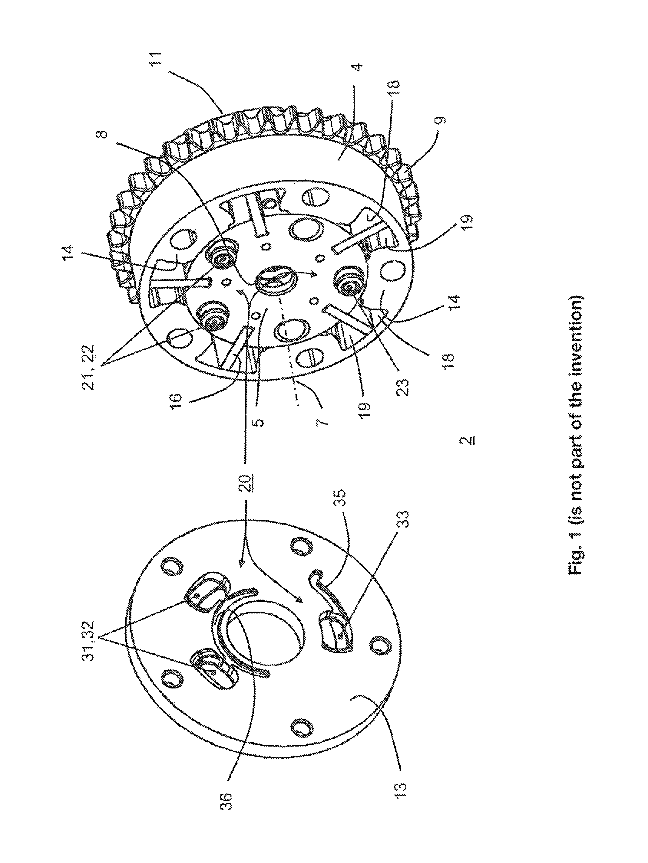
[0027]Reference is hereby made to FIG. 1, which shows a perspective view of a hydraulic camshaft adjuster 2 according to the prior art, which is not the subject matter of the present invention. Illustrated camshaft adjuster 2 includes a stator 4, in which a rotor 5 is rotatably supported around a rotation axis 7. Rotor 5 has a central bore 8 for fixing to a camshaft, which is not illustrated. A central screw, for example, which may be screwed to the camshaft, is guided through this bore 8. Stator 4 includes an outer wheel 9, which has an outer toothing. Via the outer toothing, stator 4 is coupled with a crankshaft, which is not illustrated, with the aid of a driving means, which is also not illustrated.

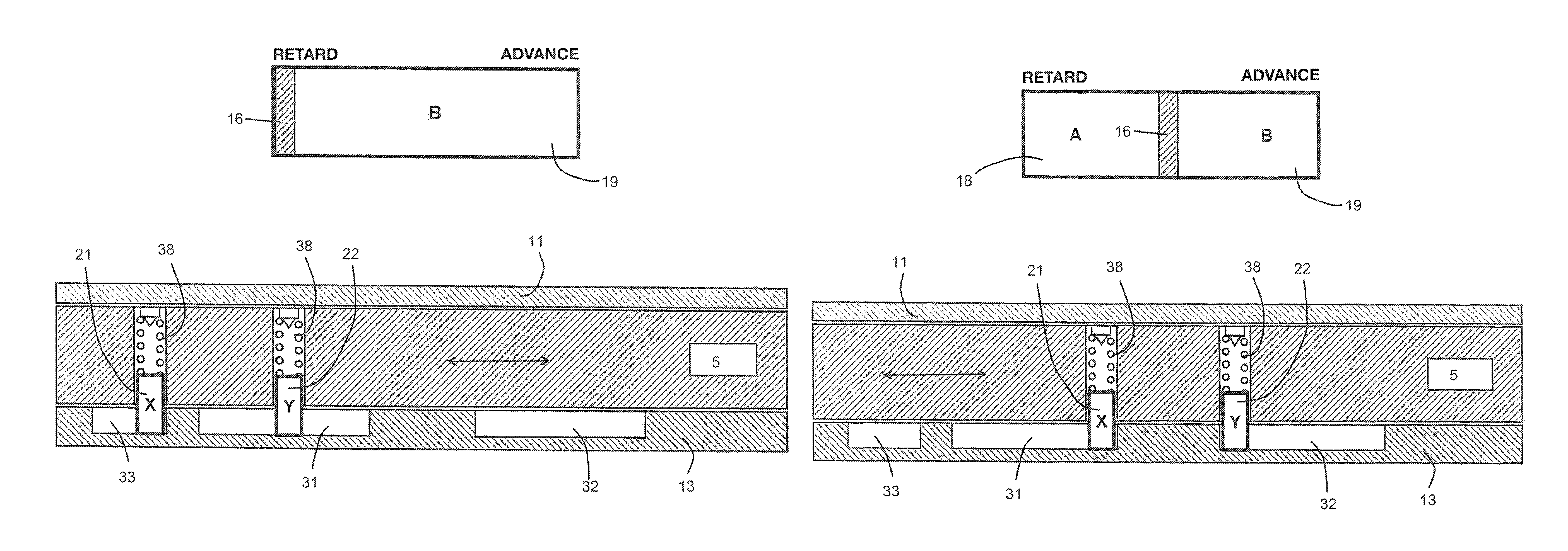
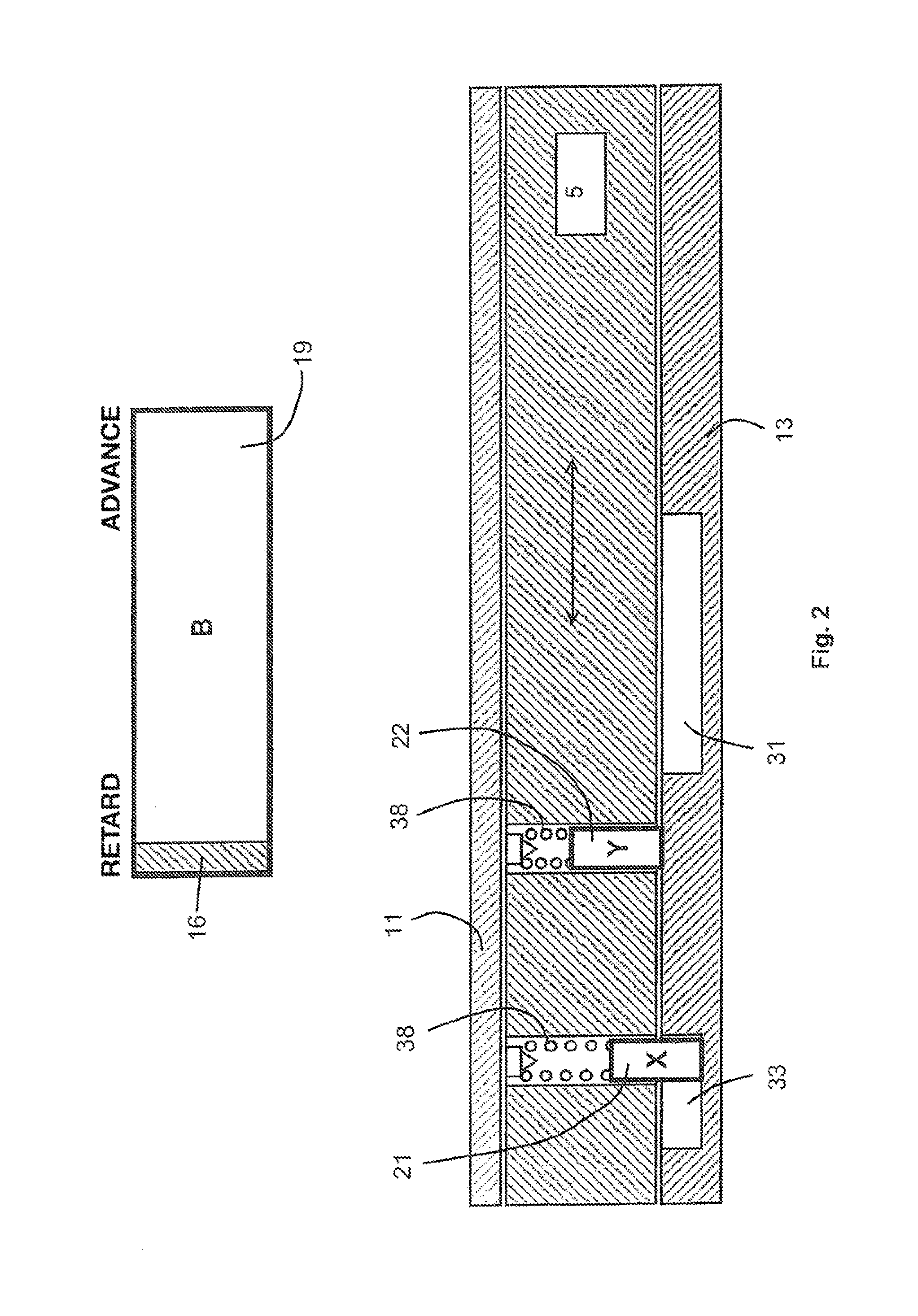
[0028]Rotor 5 is supported in stator 4 between a sealing cover 11, which is not visible, and a locking cover 13, which is shown in the open state. A number of separating elements 14 project from stator 4 into the interior. One vane element 16 of rotor 5 is situated between two adjacen...


PUM


Abstract

A camshaft adjuster having a first component, a second component rotatable relative to the first component within an angular range, and a locking device for locking the first component relative to the second component. The locking device includes a first locking bolt and a second locking bolt on the first component and a central slotted guide on the second component, and wherein the two locking bolts are movably guided between a locking position and an unlocking position and engage in the central slotted guide in a central angular position relative to one another in their locking position. At least one terminal slotted guide, in which the first locking bolt or the second locking bolt engages in its locking position in a terminal angular position differing from the central angular position of the components, is arranged on the second component.

Description

[0001]The present invention relates to a camshaft adjuster having a first component, a second component which is rotatable relative to the first component around a rotation axis within an angular range and a locking device for locking the first component with respect to the second component, the locking device including a first locking bolt and a second locking bolt on the first component and at least one central slotted gate on the second component, and the two locking bolts being movably guided between a locking position and an unlocking position and engaging with the one central slotted gate in their locking position in a central angular position of the components with respect to each other.BACKGROUND[0002]Camshaft adjusters are industrial modules for adjusting the phase angle between a crankshaft and a camshaft in an internal combustion engine. One of the components, also known as the stator, is rotatably fixedly connected to the crankshaft. The other component, also known as th...

Claims


Application Information

Patent Timeline
Patent Type & Authority Patents(United States)
IPC IPC(8): F01L1/34F01L1/344
CPCF01L1/34413F01L1/3442F01L2001/34459F01L2001/34466
Inventor BUSSE, MICHAEL
Owner SCHAEFFLER TECH AG & CO KG
Why Eureka
Try Eureka