
Adjustable door mounting system

a door and hinge technology, applied in the direction of door/window fittings, construction, building components, etc., can solve the problems of difficult removal and replacement of frames, high labor intensity, and high cos

Active Publication Date: 2015-11-10
SCHLAGE LOCK
View PDF15 Cites 11 Cited by
  • Summary
  • Abstract
  • Description
  • Claims
  • Application Information

AI Technical Summary

Benefits of technology

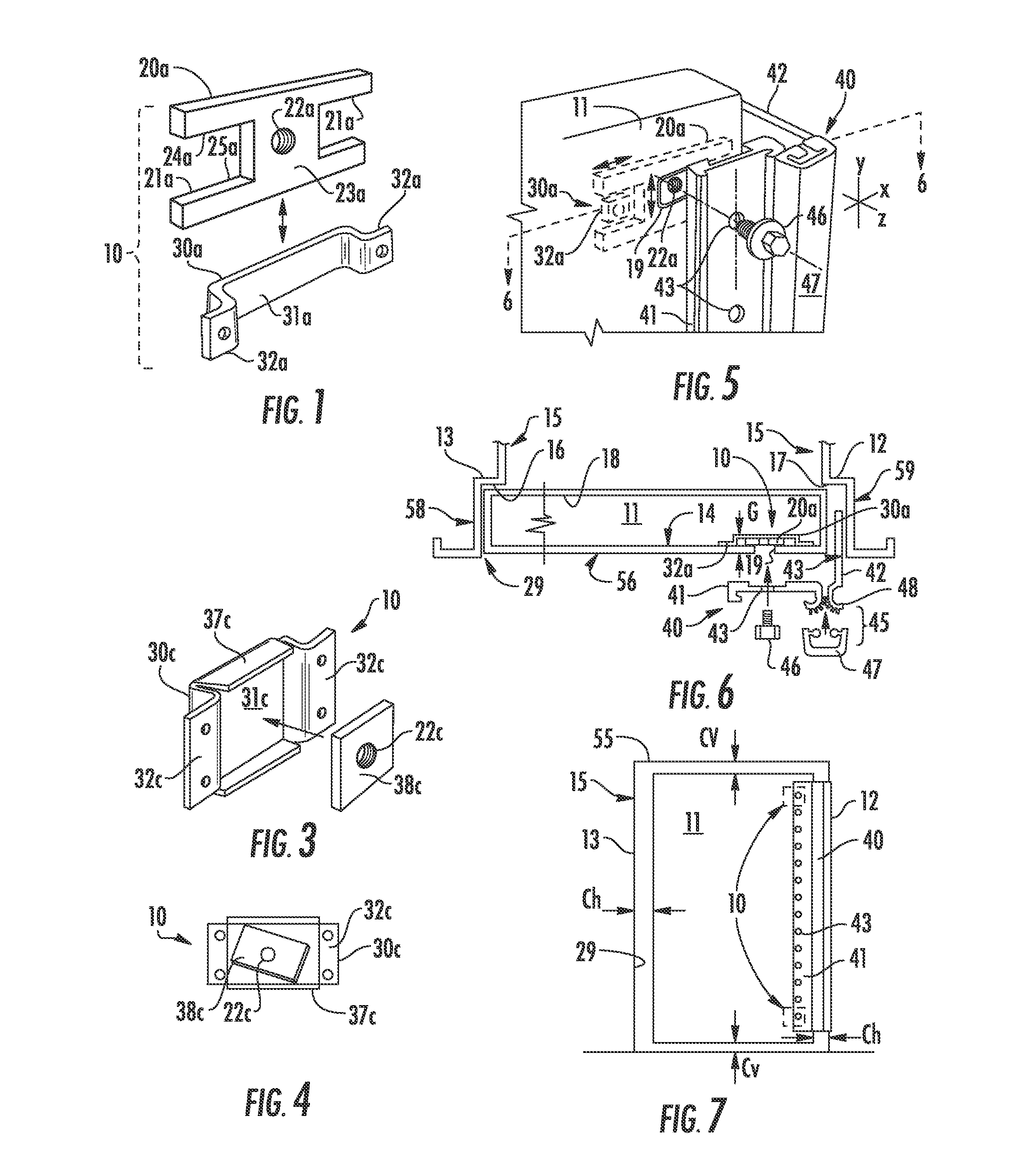
"The present invention provides a door and hinge attachment system that allows for three-dimensional adjustability of a door in relation to the frame. This enables installers to make vertical and horizontal adjustments in the plane of the door relative to the frame, as well as perpendicular to the frame in a fourth axis. The system includes a user-adjustable door insert or captive nut assembly with a movable adjusting plate and a holding bracket mounted to the door or frame. The adjusting plate is held in the bracket and can be engaged with a threaded fastener inserted through the door leaf or the hinge leaf. The system allows for proper alignment and mounting of the door in new or deteriorated door frames."

Problems solved by technology

However, in the vast majority of cases, the frame is the most difficult component to remove and replace.
Metal frames, which are frequently used in commercial buildings, are often anchored to concrete construction, making their removal and replacement very difficult, and involves many operations including demolition and removal, masonry, new frame installation and the repainting of both walls and frames.
The fitting of new frames in any type of construction to achieve true and plumb openings, is a task which requires great skill and is extremely costly.
Adding to the complexity is the fact that these frames may have originated from a different manufacturer, even in the same building.
Building settling problems and masonry failures add to the difficulty of obtaining a complete dimensional analysis on a frame-by frame basis.
The preparation of new, properly fitted replacement doors to these specifications on a door-by-door basis may be cost-prohibitive.

Method used


Image

  • Adjustable door mounting system
  • Adjustable door mounting system
  • Adjustable door mounting system

Examples


Embodiment Construction

[0060]The description of illustrative embodiments according to principles of the present invention is intended to be read in connection with the accompanying drawings, which are to be considered part of the entire written description. In the description of embodiments of the invention disclosed herein, any reference to direction or orientation is merely intended for convenience of description and is not intended in any way to limit the scope of the present invention. Relative terms such as “lower,”“upper,”“horizontal,”“vertical,”“above,”“below,”“up,”“down,”“top” and “bottom” as well as derivative thereof (e.g., “horizontally,”“downwardly,”“upwardly,” etc.) should be construed to refer to the orientation as then described or as shown in the drawing under discussion. These relative terms are for convenience of description only and do not require that the apparatus be constructed or operated in a particular orientation unless explicitly indicated as such. Terms such as “attached,”“affi...


PUM


Abstract

A three-dimensional adjustable door mounting system and method for aligning and installing a hinged door within a frame. In one embodiment, the mounting system includes one or more captive nuts mounted to the door. The captive nut includes a movable adjusting plate retained by a stationary holding bracket mounted to the door. A threaded fastener inserted through a hinge door leaf and into the adjusting plate allows an installer to move and adjust the position of the hinge relative to the door in a first plane. In other embodiments, captive nuts may further be affixed to the door frame. A threaded fastener inserted through a hinge frame leaf and into the adjusting plate allows an installer to move and adjust the position of the hinge and door relative to the frame in a second plane different than the first plane.

Description

CROSS-REFERENCE TO RELATED APPLICATIONS[0001]This application claims priority to U.S. Provisional Application No. 61 / 146,507 filed Jan. 22, 2009 and U.S. Provisional Application No. 61 / 253,957 filed Oct. 22, 2009, the contents of both which are incorporated herein by reference in their entireties.FIELD OF INVENTION[0002]The present invention relates to door and hinge mounting systems, and more particularly relates to a door mounting system and method providing three-dimensional adjustment of an ingress / egress door in a door frame.BACKGROUND OF THE INVENTION[0003]More and more, as buildings age, it has become increasingly desirable to replace their doors. However, in the vast majority of cases, the frame is the most difficult component to remove and replace. With wood construction, there is normally a decorative outer casing that hides the juncture between the wall material (e.g., sheetrock or plaster) and the wooden frame. The frame itself is typically shimmed with wedges to achieve...

Claims


Application Information

Patent Timeline
Patent Type & Authority Patents(United States)
IPC IPC(8): E05D7/04E05D5/02E05D3/12E05D7/00
CPCE05D7/04E05D3/122E05D5/0238E05D7/009E05Y2900/132
Inventor BAER, AUSTIN R.
Owner SCHLAGE LOCK
Learn More