
Aircraft ventilation device

a ventilation device and aircraft technology, applied in the direction of machines/engines, transportation and packaging, electric generator control, etc., can solve the problems of insufficient refrigeration cycles of aircraft, insufficient current systems, and insufficient cooling of heat exchangers, etc., to achieve greater efficiency and maximum electrical energy

Active Publication Date: 2015-11-10
AIRBUS OPERATIONS (SAS) +1
View PDF9 Cites 0 Cited by
  • Summary
  • Abstract
  • Description
  • Claims
  • Application Information

AI Technical Summary

Benefits of technology

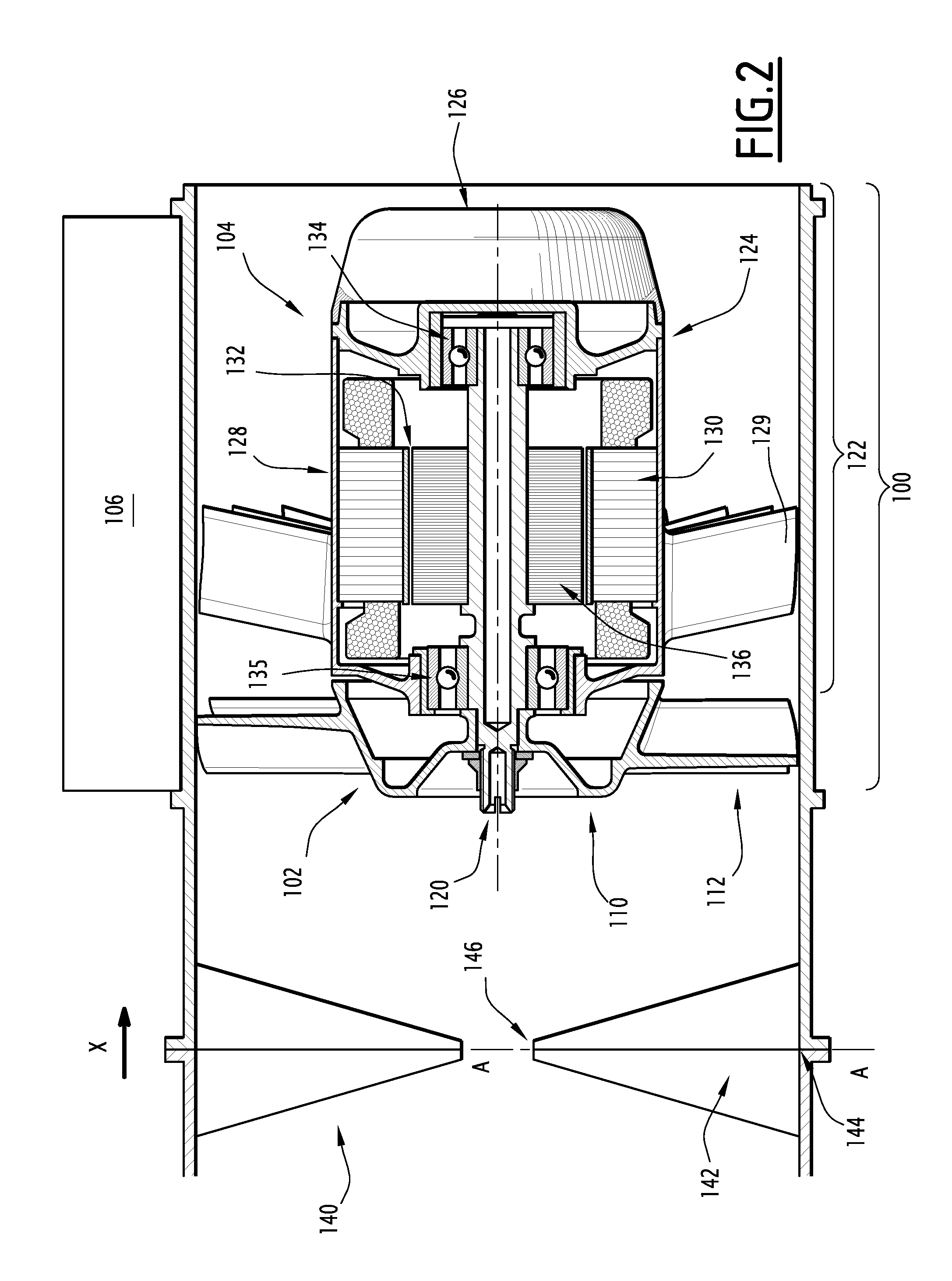
[0013]To that end, the invention relates to a ventilation device of the aforementioned type, the inverter being reversible and, in an energy generating mode of the ventilation device, able to convert the electrical energy provided by the rotary machine when the latter part is mechanically driven by the wheel and to inject that converted electrical energy into the power supply network, characterized in that the ventilation device includes a controller and a distributor extending transversely in front of the wheel, the distributor including vanes extending radially, the controller being suitable, in the motor supply mode, for controlling the orientation of the vanes in a first position, maximizing an air flow generated by the wheel when it is driven by the rotary machine, and, in the energy generating mode, controlling the orientation of the vanes in a second position, maximizing the electrical energy supplied by the rotary machine when it is driven by the wheel, itself being driven by a flow of air passing through the distributor, the first and second positions being distinct from one another.

Problems solved by technology

On the other hand, when the aircraft is on the ground, the natural convection is not sufficient to cool the heat exchanger satisfactorily.
In the absence of a complementary device, the refrigeration cycles of the aircraft may no longer perform their role.
However, current systems are not fully satisfactory.
Although the current ventilation devices do serve their purpose well when the aircraft is on the ground, they are useless when the aircraft is in flight.

Method used


Image

  • Aircraft ventilation device
  • Aircraft ventilation device
  • Aircraft ventilation device

Examples


Embodiment Construction

[0029]In all of the following, “on the ground” refers to the fact that the aircraft is not flying, or flying at a low altitude, commonly below 10,000 feet. “In flight” refers to the fact that an aircraft is flying at a high altitude, commonly above 10,000 feet.

[0030]Moreover, the term “cylinder” should be understood in the broad sense and includes both elements with a circular base and elements with an ovoid, triangular, or quandrangular base, or any other type of closed contour. The term “cylindrical in revolution” designates cylinders with a circular base.

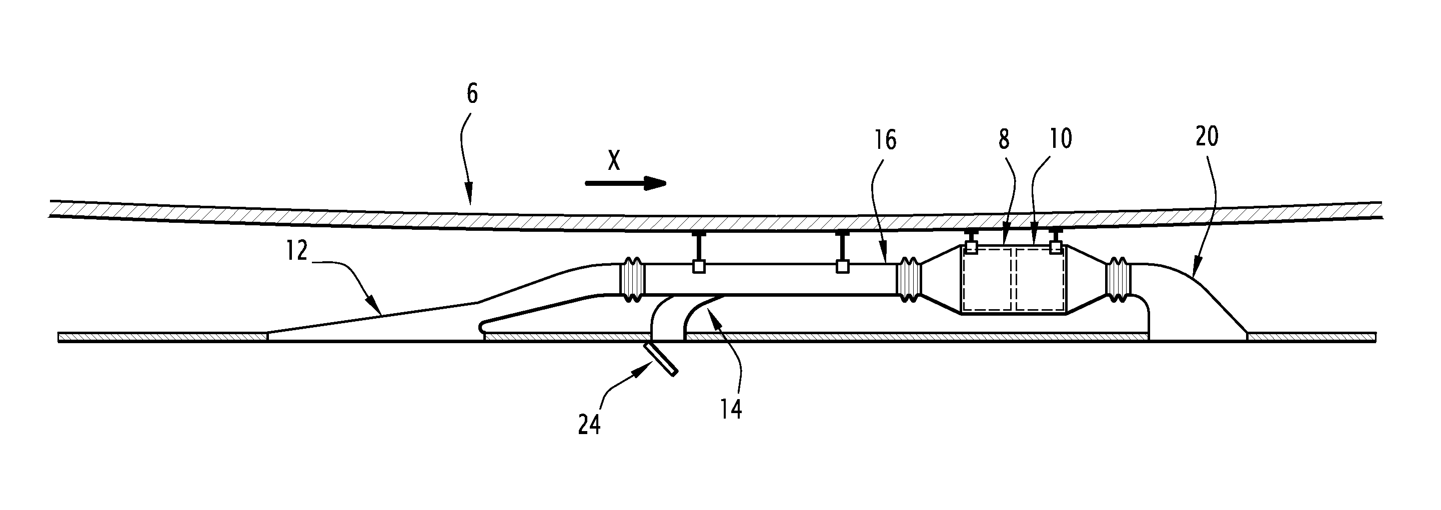
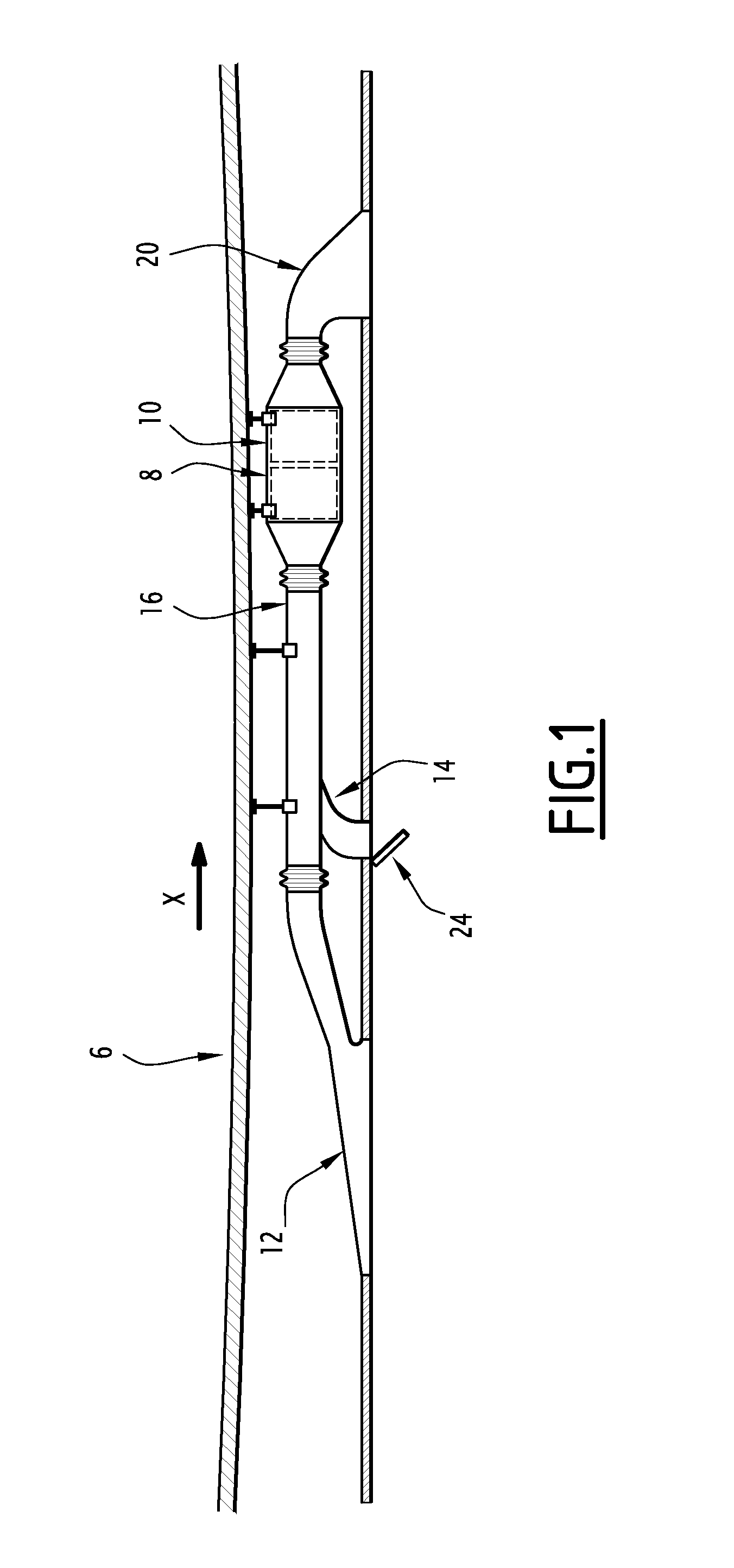
[0031]FIG. 1 illustrates an air conduit 6 of an aircraft, successively including a heat exchanger 8 and a ventilation device according to the invention 10.

[0032]The air conduit 6 extends in a longitudinal direction X going from the front to the back of the aircraft. It successively includes, from front to back, a dynamic air intake 12, a cylindrical portion 16, and an air outlet 20. It also includes a fan air inlet 14, pierced in...


PUM


Abstract

The ventilation device according to the invention includes a fan and an inverter. The fan comprises a rotary electrical machine and a wheel for setting an air flow into motion, integral with the rotary machine to set it in rotation. The inverter is connected to the rotary machine and, in one motor power mode of the ventilation device, is suitable for forming the supply current of the rotary machine. The inverter is suitable for being connected to a power supply network. The inverter is reversible and is, in a generating mode of the ventilation device, suitable for converting the electrical energy supplied by the rotary machine when it is driven mechanically by the wheel and injecting said converted electrical energy into the power supply network.

Description

CROSS-REFERENCE TO RELATED APPLICATIONS[0001]This application claims the benefit of French Application No. 1051124 filed Feb. 17, 2010 which is hereby expressly incorporated by reference in its entirety.BACKGROUND OF THE INVENTION[0002]1. Field of the Invention[0003]The present invention relates to an aircraft ventilation device, of the type comprising:[0004]a fan comprising a rotary electrical machine and a wheel for setting an air flow in motion, integral with the rotary machine for setting in rotation thereof; and[0005]an inverter to which the rotary machine is connected and which, in one motor power mode of the ventilation device, is suitable for forming the feed current from the rotary machine, said inverter being suitable for being connected to a power supply network.[0006]2. Description of the Related Art[0007]Ventilation devices are known equipping various types of aircrafts, and particularly airplanes, serving for cooling, when the aircraft is on the ground, of a heat excha...

Claims


Application Information

Patent Timeline
Patent Type & Authority Patents(United States)
IPC IPC(8): F04D27/00B64D13/08B64D41/00
CPCB64D13/08B64D41/007F04D27/002
Inventor DARNIS, OLIVIER
Owner AIRBUS OPERATIONS (SAS)
Learn More