
Method for combining a road sign recognition system and a lane detection system of a motor vehicle

a technology of lane detection and recognition system, which is applied in the detection of traffic movement, instruments, computing, etc., can solve the problems of restricted functionality of such driver assistance system, and achieve the effect of improving the service quality of these two systems

Active Publication Date: 2015-11-03
CONTI TEMIC MICROELECTRONIC GMBH
View PDF24 Cites 5 Cited by
  • Summary
  • Abstract
  • Description
  • Claims
  • Application Information

AI Technical Summary

Benefits of technology

The invention is a method that improves the ability of a road sign recognition system and a lane detection system to identify signs and lanes without relying on information from digital maps or satellite-based navigation systems. Additionally, the invention suggests using information from the lane course to generate construction-site-indicating information to help drivers navigate through construction zones. This helps ensure the accuracy of road signs and reduces the risk of accidents.

Problems solved by technology

However, the functionality of such driver assistance systems may be restricted if the navigation-based data are not available, i.e., if the additional input signals of a satellite-based navigation system are not available to these systems.

Method used


Image

  • Method for combining a road sign recognition system and a lane detection system of a motor vehicle
  • Method for combining a road sign recognition system and a lane detection system of a motor vehicle

Examples


Embodiment Construction

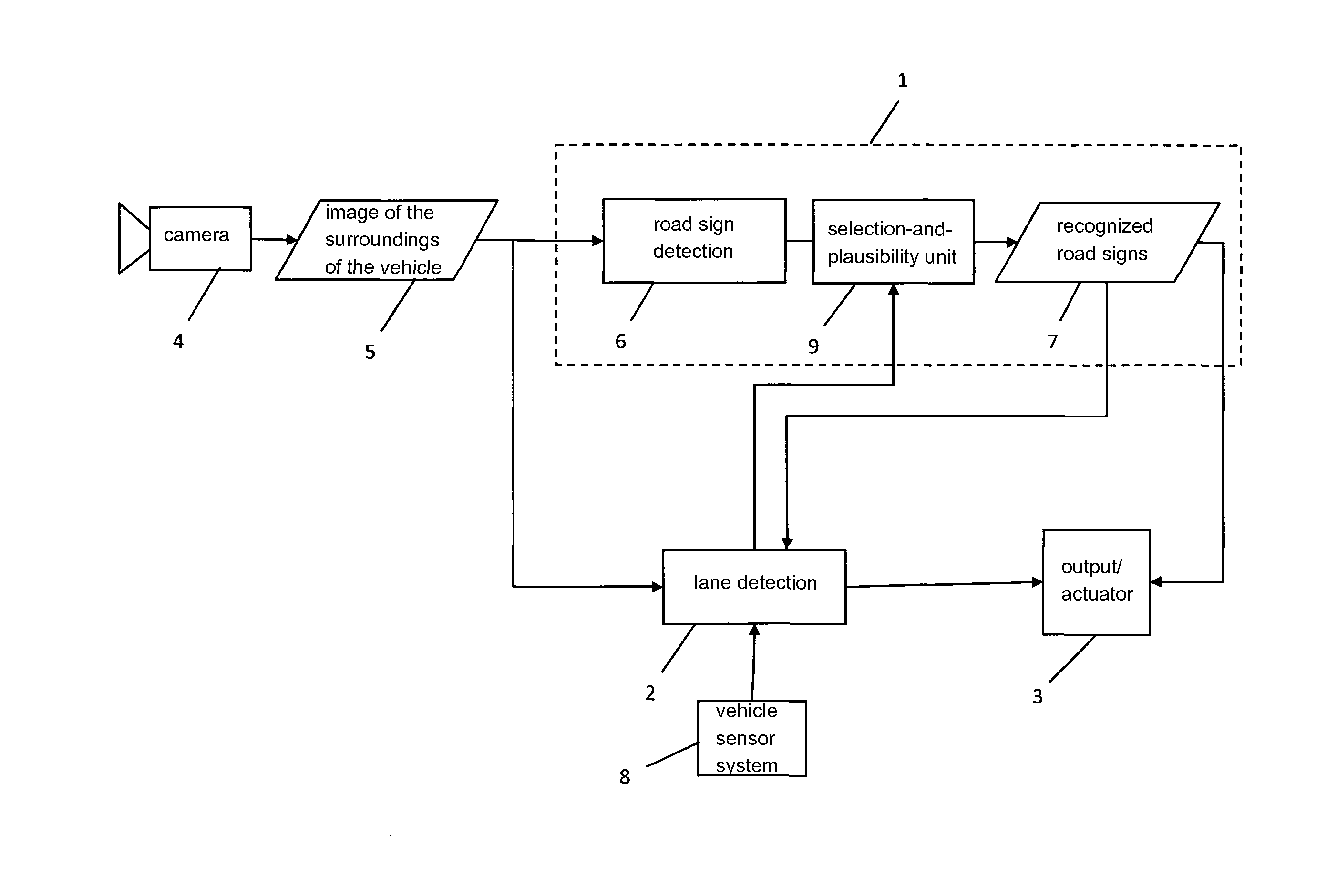
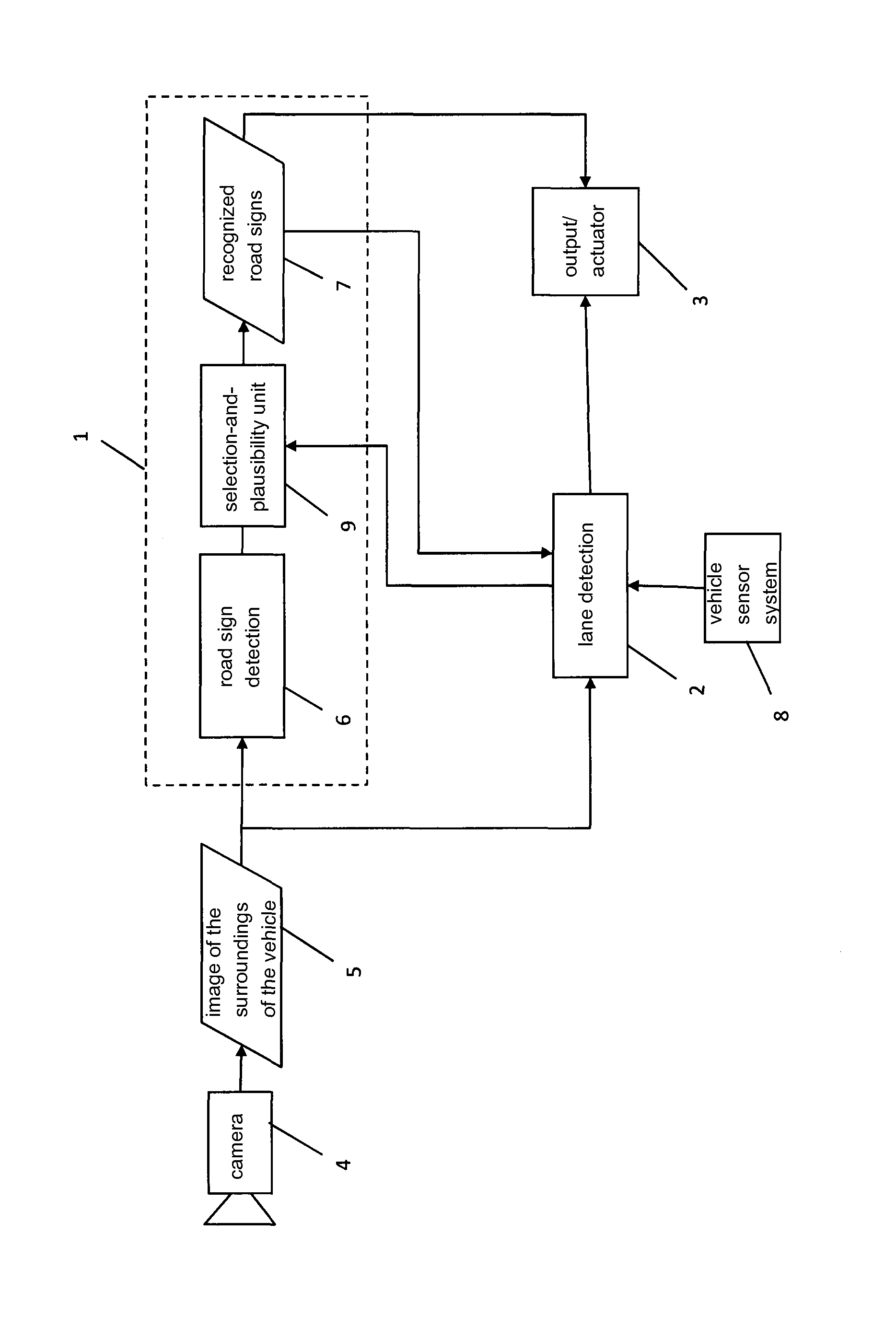
[0025]In the following, the invention will be explained in greater detail with reference to a single FIG. 1. Said FIG. 1 shows a schematic block diagram of a driver assistance system of a motor vehicle. Said driver assistance system is made up of a road sign recognition system 1 and a lane detection system 2. Said motor vehicle is not shown.

[0026]Said driver assistance system also comprises a video camera 4 with a downstream storage unit 5. The image data of the surroundings of the motor vehicle acquired by the camera 4 are stored in the form of images in said storage unit 5. Said camera 4 covers the region in front of the motor vehicle and is usually arranged on the interior mirror of the motor vehicle. In addition or alternatively, one camera 4 each may be mounted on the exterior mirrors in order to be able to cover the regions at the sides of the motor vehicle.

[0027]The image data of the storage unit 5 are supplied to both the road sign recognition system 1 and the lane detection...


PUM


Abstract

A method combines a road sign recognition system and a lane detection system of a motor vehicle. The road sign recognition system generates road sign information from sensor data of a camera-based or video-based sensor system and the lane detection system generates lane course information from the sensor data. Meaning-indicating data for road signs are generated from the lane course information, and are used to check the plausibility of and / or to interpret the road sign information. Data indicating the course of the lane are generated from the road sign information, and are used to check the plausibility of and / or to interpret the lane course information.

Description

TITLE OF THE INVENTION[0001]1. Field of the Invention[0002]The invention relates to a method for combining a road sign recognition system and a lane detection system of a motor vehicle.[0003]2. Background Information[0004]Modern driver assistance systems assist the driver in driving his or her vehicle. A great number of such systems are based on, e.g., lane detection and road sign recognition. Lane departure warning, lane assignment for longitudinal control systems or a function for intervening in the steering process for the purpose of lane keeping can be realized by means of robust and reliable lane detection.[0005]Such lane detection systems and road sign recognition systems are usually based on camera systems (in particular, on video camera systems) that are fastened to the interior mirror of the motor vehicle or to exterior mirrors thereof.[0006]The fact that such driver assistance systems obtain additional information from a navigation system and / or various driver assistance s...

Claims


Application Information

Patent Timeline
IPC IPC(8): G06K9/00G08G1/0967G08G1/16G08G1/0962
CPCG06K9/00798G08G1/09623G08G1/096716G08G1/096775G08G1/16G08G1/167G06V20/588B60W30/12G08G1/04
Inventor MEIS, URBANGUTMANN, CHRISTIANSCHORN, MATTHIASKRISTENSEN, STEEN
Owner CONTI TEMIC MICROELECTRONIC GMBH
Learn More