
Method and apparatus for refurbishing turbine components

a technology for turbine components and apparatus, applied in the direction of electrolysis process, electrolysis components, etc., can solve the problems of oxidation and corrosion wear of gt components, reduced performance, and current cleaning methods that do not fully restore the surface finish of a new blad

Inactive Publication Date: 2015-10-20
GENERAL ELECTRIC CO
View PDF23 Cites 5 Cited by
  • Summary
  • Abstract
  • Description
  • Claims
  • Application Information

AI Technical Summary

Benefits of technology

The present invention provides a method for refurbishing turbine components by using electro-polishing to remove surface layers of the components. The method includes immersing the components in a buffered electrolytic solution and passing electrical energy through the components to remove surface layers while preventing corrosion. An electro-polishing apparatus is also provided to support the turbine assembly and distribute the electrical energy to the components. The invention allows for efficient and effective reconditioning of turbine components without the need for excessive labor or downtime.

Problems solved by technology

Gas turbines (GT) are often subjected to harsh operating conditions and prolonged operation times, leading to oxidation and corrosion wear of GT components.
For GT compressor rotor blades, these factors cause surface finish degradation, adversely affecting the aerodynamic performance of the blades by increasing the coefficient of drag (CD) and resulting in reduced performance.
However, current methods of cleaning do not fully restore the surface finish to that of a new blade.
Manual scrubbing and / or cleaning of the rotor blades is a time-consuming process which results in a less than optimal surface finish of the blade.
However, current electro-polishing practices require disassembly and / or transportation of the GT.
Disassembly and transportation increase the GT downtime, resulting in lost productivity.

Method used


Image

  • Method and apparatus for refurbishing turbine components
  • Method and apparatus for refurbishing turbine components
  • Method and apparatus for refurbishing turbine components

Examples


Embodiment Construction

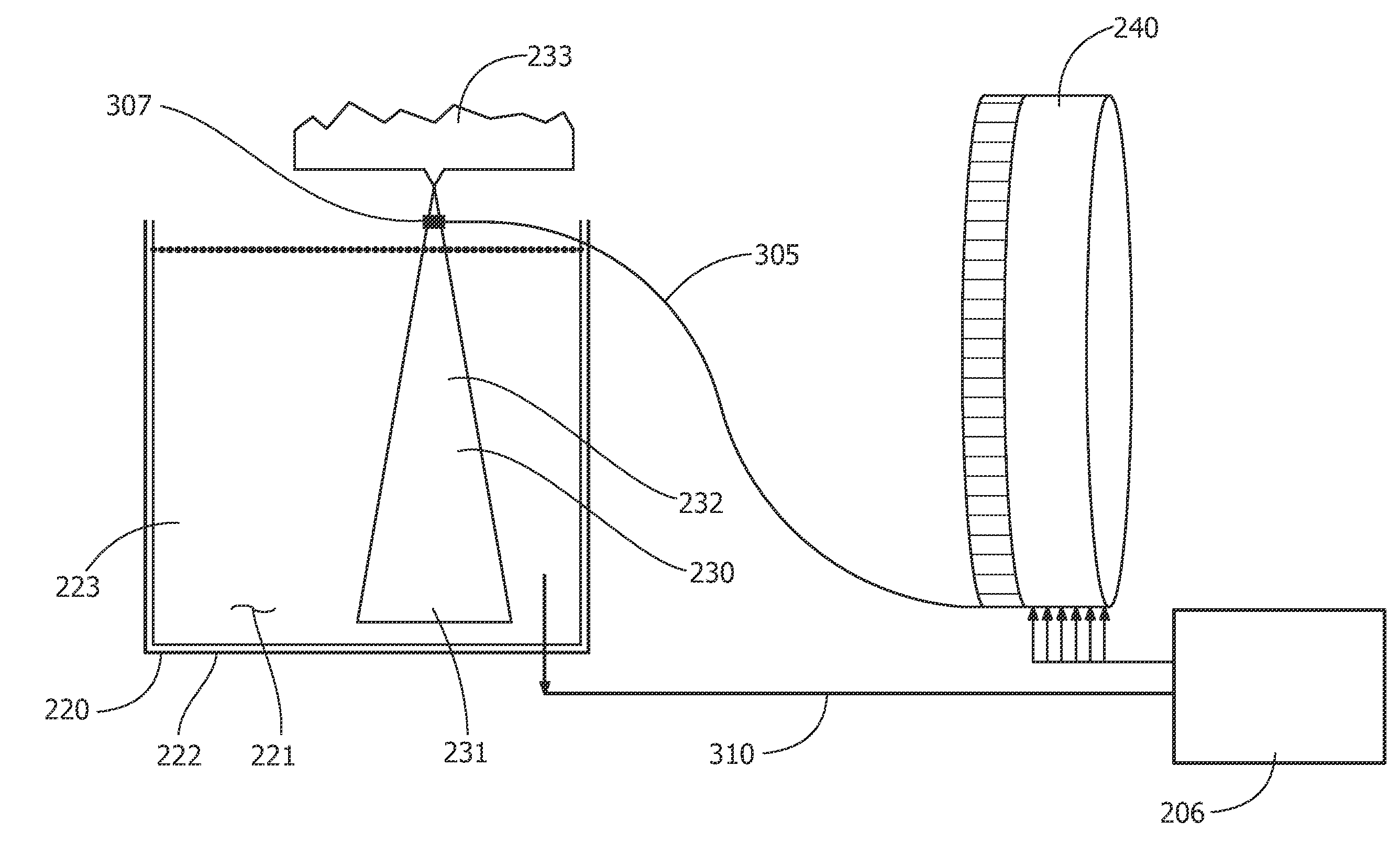
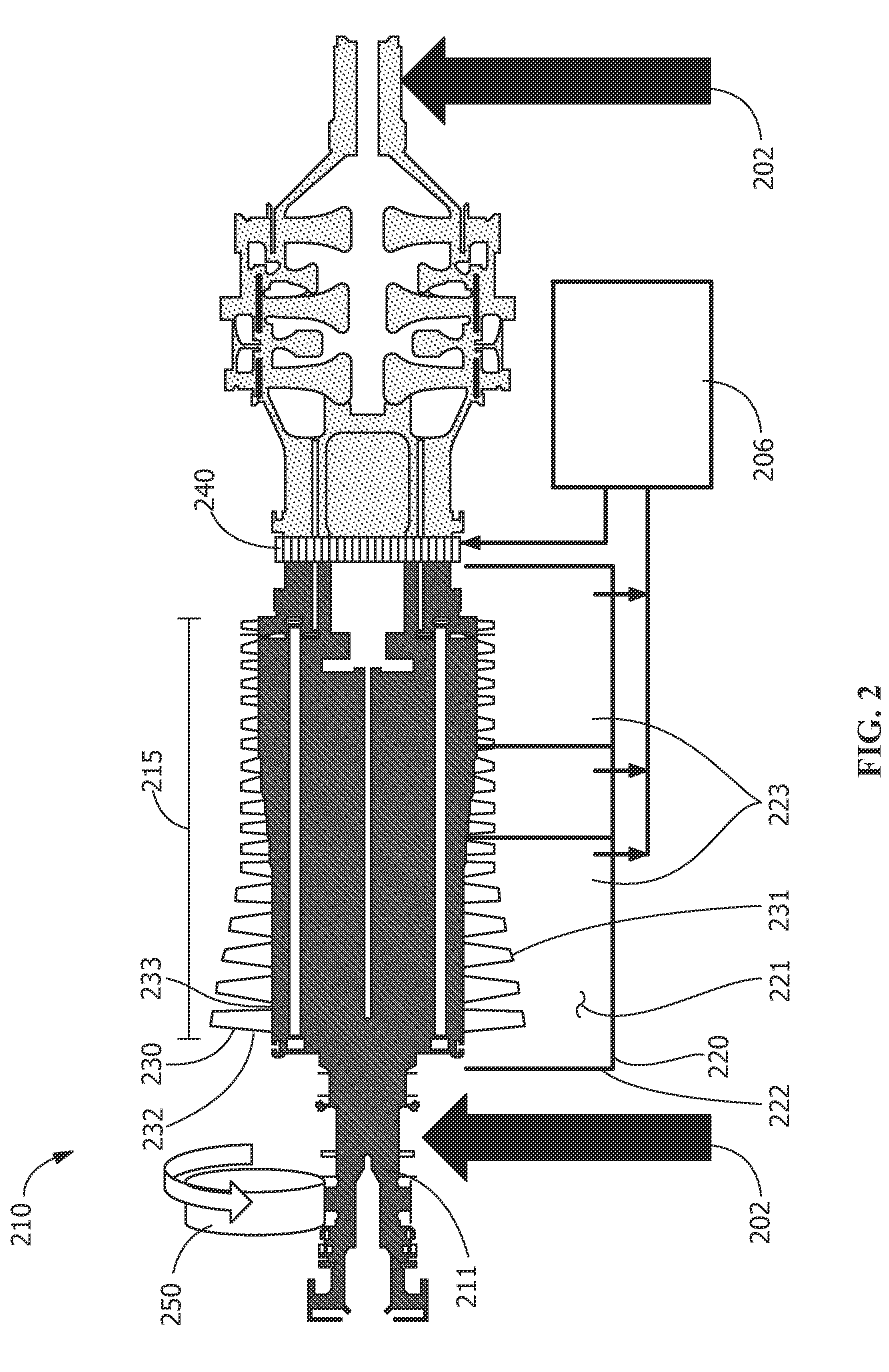
[0015]Provided are exemplary refurbishing apparatus and in-situ refurbishing methods for refurbishing a plurality of rotatable components of a turbine assembly. The rotatable components lose their aerodynamic efficiency after operation in a turbine due to one or more of oxidation, corrosion and / or minor impacts from foreign objects, such as sand or dust which may be ingested, all of which may affect a surface finish of the rotatable components. The type and amount of surface damage is dependent upon the environment in which the turbine operates. For the purposes of this application, in-situ means at the operational site or venue of the turbine. Embodiments of the present disclosure, in comparison to apparatus and methods not utilizing one or more features disclosed herein, decrease turbine downtime, decrease turbine transportation, decrease labor for polishing, increase rotor blade polishing efficiency, increase rotor blade polishing effectiveness, decrease lost productivity, decrea...


PUM

PropertyMeasurementUnit
timeaaaaaaaaaa
volumeaaaaaaaaaa
electrical energyaaaaaaaaaa

Abstract

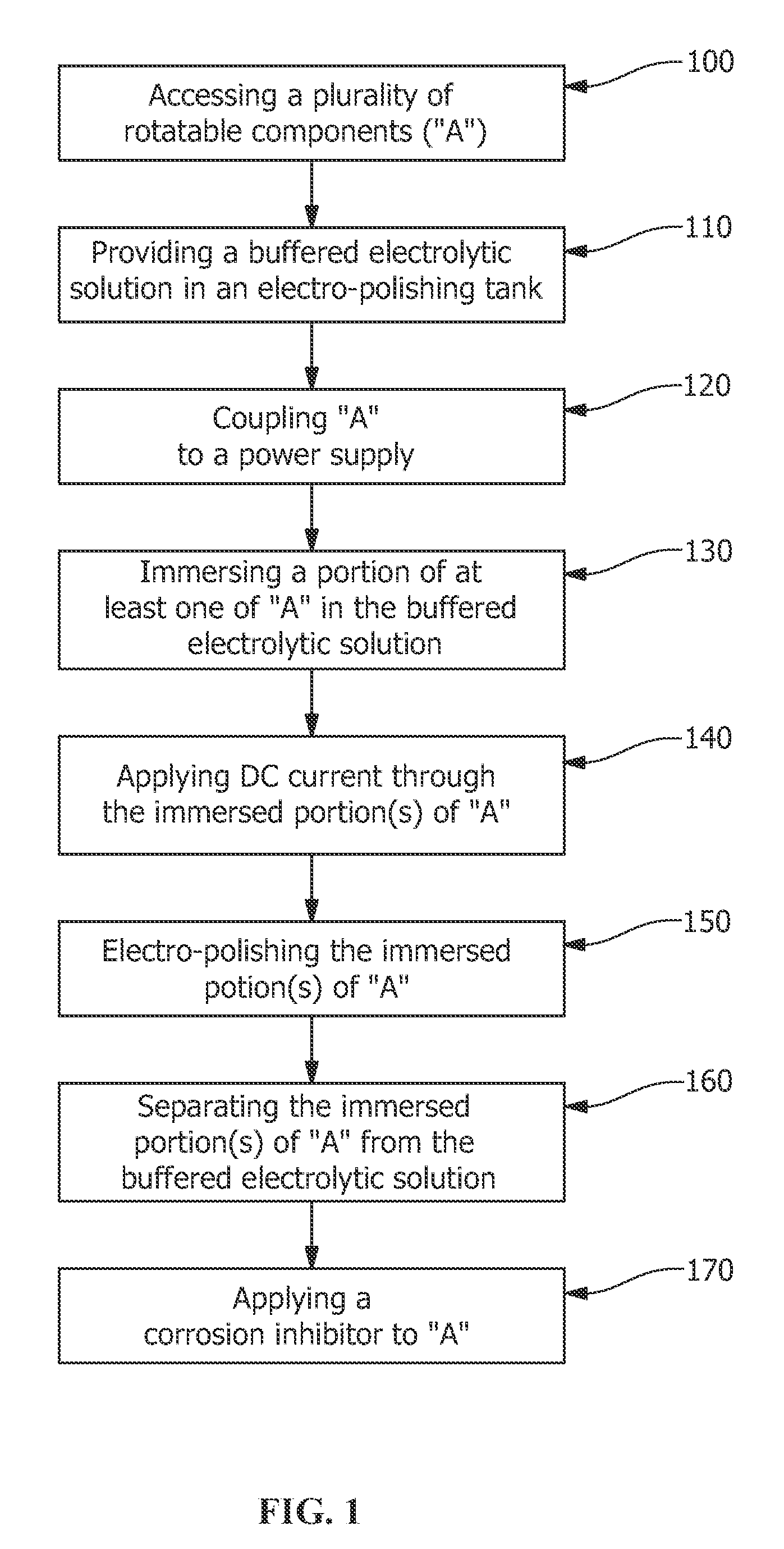
A refurbishing method, refurbishing apparatus and refurbished article are provided. The refurbishing method includes accessing a plurality of rotatable components attached to a turbine assembly, the turbine assembly being a portion of a turbomachine, providing a predetermined volume of a buffered electrolytic solution in an electro-polishing tank, coupling the plurality of rotatable components to a power supply, immersing an immersion portion of at least one of the plurality of rotatable components in the buffered electrolytic solution, passing an electrical energy through the immersion portion of at least one of the plurality of rotatable components while the immersion portion is immersed in the buffered electrolytic solution, wherein an electrical flux to the immersion portion electro-polishes the immersion portion, separating the immersion portion from the buffered electrolytic solution, and applying a corrosion inhibitor to the plurality of rotatable components.

Description

FIELD OF THE INVENTION[0001]The present invention is directed to an apparatus and methods for refurbishing turbine components. More specifically, the present invention is directed to an apparatus and methods for electro-polishing turbine components.BACKGROUND OF THE INVENTION[0002]Gas turbines (GT) are often subjected to harsh operating conditions and prolonged operation times, leading to oxidation and corrosion wear of GT components. For GT compressor rotor blades, these factors cause surface finish degradation, adversely affecting the aerodynamic performance of the blades by increasing the coefficient of drag (CD) and resulting in reduced performance. Usually during major inspections, which are conducted at predetermined intervals, the rotor blades and stator vanes are manually scrubbed and / or cleaned to partially restore the surface finish of the blades and vanes. The scrubbing and / or cleaning of the rotor blades and vanes improves the surface finish, partially restoring GT outpu...

Claims


Application Information

Patent Timeline
Patent Type & Authority Patents(United States)
IPC IPC(8): B23H9/10C25F3/16C25F7/00
CPCC25F3/16B23H9/10C25F7/00
Inventor DIMASCIO, PAUL STEPHENSCIPIO, ALSTON ILFORDDAVIS, DALE J.EKANAYAKE, SANJI
Owner GENERAL ELECTRIC CO
Learn More