
Ship maneuvering device

a maneuvering device and ship technology, applied in the direction of steering initiation, vessel parts, vessel construction, etc., can solve the problems of difficulty in maneuvering the ship by slipping the clutch (so-called semi-clutch), difficulty in operating the berthing and unberthing of the ship for an unskilled operator, and difficulty in maneuvering the ship by some operators. , to achieve the effect of easy maneuvering of the ship, and improved engine rotation speed

Active Publication Date: 2015-10-20
YANMAR POWER TECHNOLOGY CO LTD
View PDF10 Cites 3 Cited by
  • Summary
  • Abstract
  • Description
  • Claims
  • Application Information

AI Technical Summary

Benefits of technology

Enables sailing at speeds lower than the low idling rotation speed, improving maneuverability by allowing the operator to adjust the sailing speed according to the situation, reducing the risk of high-speed difficulties during berthing and unberthing, and maintaining a stable engine rotation speed for smoother operations.

Problems solved by technology

However, according to the art described in the Patent Literature 1, the troll sailing by slipping the clutch (so-called semi-clutch) cannot be performed.
Namely, sailing with a sailing speed lower than the sailing speed at the low idling rotation speed of the engine cannot be performed, whereby the sailing speed may be too high so as to make the maneuvering of the ship difficult for some operators.
For example, at the time of berthing and unberthing of the ship, the sailing speed may be too high so as to make the operation of the berthing and unberthing of the ship difficult for an unskilled operator unfamiliar to the maneuvering of the ship.

Method used


Image

  • Ship maneuvering device
  • Ship maneuvering device
  • Ship maneuvering device

Examples


Embodiment Construction

[0048]An explanation will be given on a mode for carrying out the present invention referring to drawings.

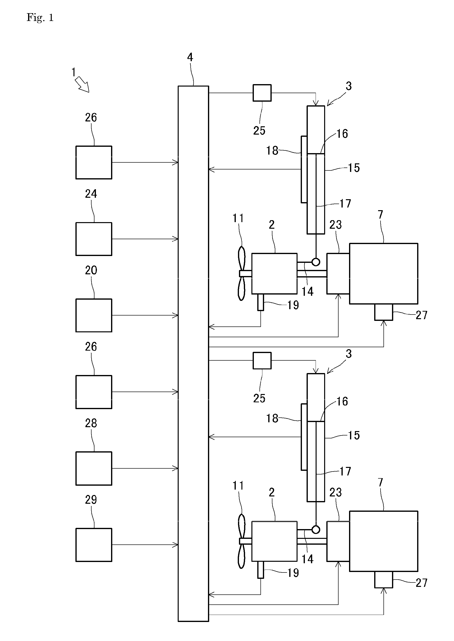
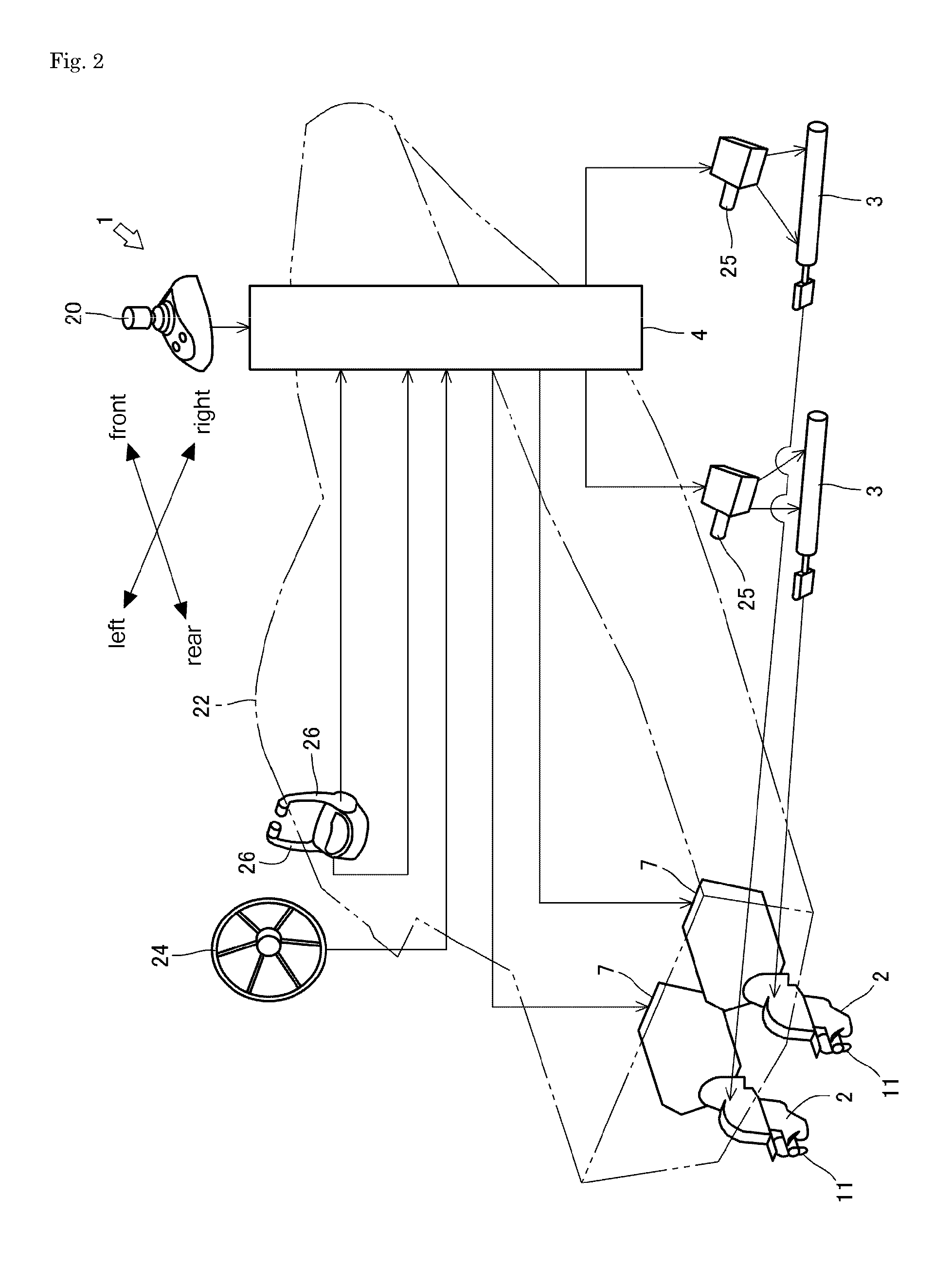
[0049]Firstly, an explanation will be given on entire construction of a maneuvering device 1 referring to FIGS. 1 to 4.

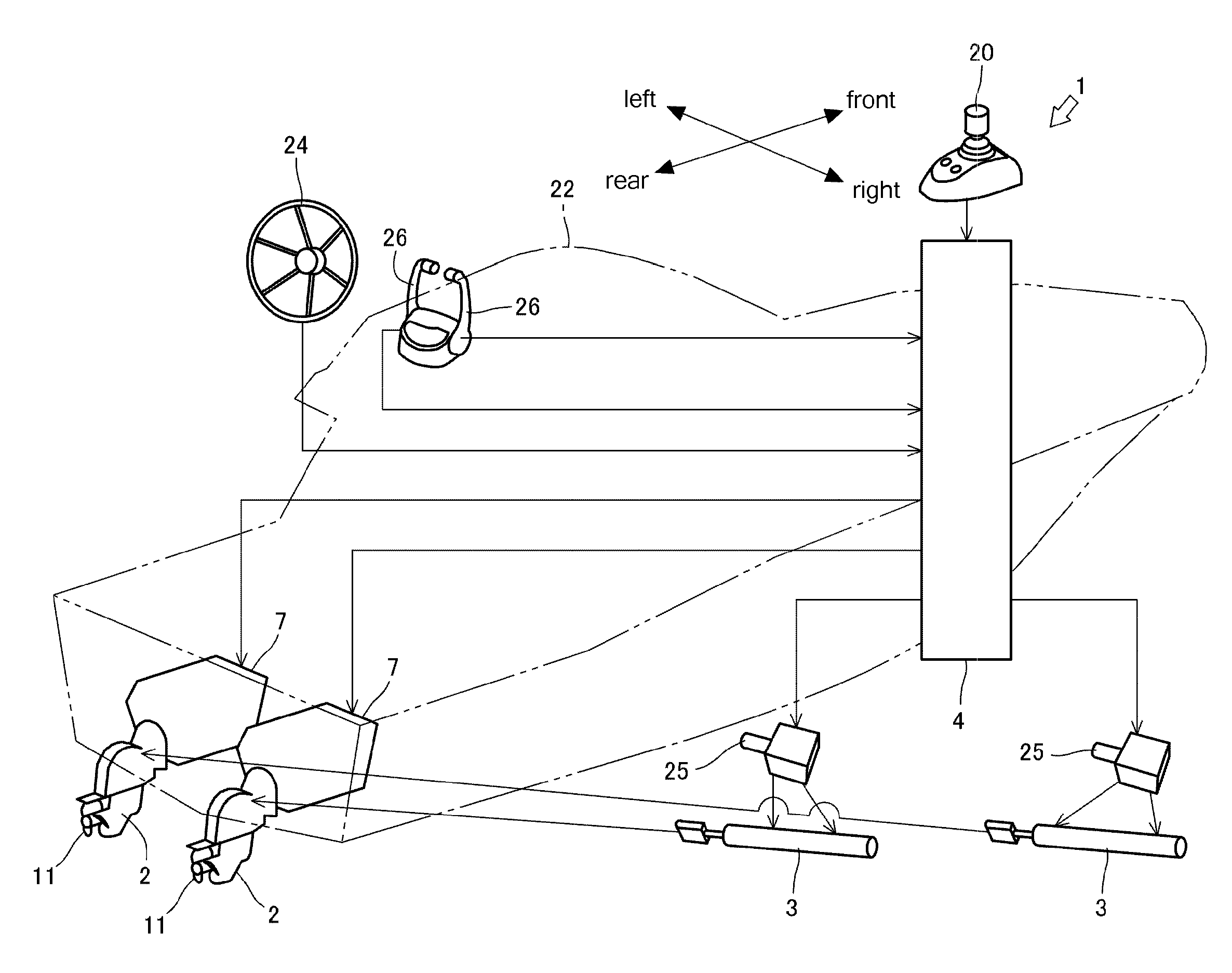
[0050]The maneuvering device 1 is so-called two-shaft (two-device) type having two outdrive devices 2. The maneuvering device 1 includes the outdrive devices 2, hydraulic cylinders 3, a control device 4 and the like.

[0051]In each of the outdrive devices 2, one of ends of an input shaft 5 is connected via an universal joint 6 to a power transmission shaft (not shown) of an engine 7 so as to be able to transmit power. Between the engine 7 and the input shaft 5, a main clutch 23 is interposed. Power transmission from the engine 7 to the input shaft 5 is turned on and off (engaged and disengaged) with the main clutch 23. The other end of the input shaft 5 is connected via a switching clutch 8 to an upper end of a drive shaft 9 so as to be able to transmit the power....


PUM


Abstract

A ship maneuvering device rotates a propeller at a lower rotational frequency than the rotational frequency of the minimum idling speed of an engine. A control device has a crawling speed navigation mode. A crawling speed navigation mode button that selects whether or not to execute the crawling speed navigation mode is connected to the control device. When the crawling speed navigation mode is selected, and the amount of operation of a joystick lever is at or beneath a baseline amount of operation Ms, the control device causes the rotational frequency N of the engine to be the rotational frequency Nlow of the minimum idling speed, and in accordance with the amount of operation of the joystick lever, varies the duty ratio D, which is the fraction of time T1 that a main clutch is engaged in a predetermined cycle T, within a range of no greater than 100%.

Description

TECHNICAL FIELD[0001]The present invention relates to a ship maneuvering device.BACKGROUND ART[0002]Conventionally, a ship is known having an engine, an outdrive device having a propeller rotated by power of the engine, and a clutch engaging and disengaging power transmission from the engine to the propeller (for example, see the Patent Literature 1). The ship described in the Patent Literature 1 is constructed so that the engine is rotated at a low idling rotation speed so as to rotate the propeller at a low speed, whereby sailing at a low speed (so-called troll sailing) is performed.[0003]However, according to the art described in the Patent Literature 1, the troll sailing by slipping the clutch (so-called semi-clutch) cannot be performed. Namely, sailing with a sailing speed lower than the sailing speed at the low idling rotation speed of the engine cannot be performed, whereby the sailing speed may be too high so as to make the maneuvering of the ship difficult for some operator...

Claims


Application Information

Patent Timeline
Patent Type & Authority Patents(United States)
IPC IPC(8): B63H21/21B63H25/42
CPCB63H21/213B63H25/42B63H20/12B63H20/14B63H20/16B63H20/20B63H23/02B63H25/02B63H2020/003B63H2023/0291B63H2025/026
Inventor HITACHI, JUNICHIHARA, NAOHIRONAKANISHI, TAKAO
Owner YANMAR POWER TECHNOLOGY CO LTD
Learn More