Gearbox for a tap changer, a tap changer and a transformer

a technology for transformers and gearboxes, applied in gearboxes, mechanical instruments, discontinuously variable inductance/transformers, etc., can solve the problems of circumstantial driving and transmission devices for this, and achieve the effect of simple and reliabl

Active Publication Date: 2015-09-08
HITACHI ENERGY LTD
View PDF4 Cites 0 Cited by
  • Summary
  • Abstract
  • Description
  • Claims
  • Application Information

AI Technical Summary

Benefits of technology

[0006]One object of the present invention is to provide a simple and reliable way of attaining a drive of a tap changer.
[0008]By using one single gearbox that from one and the same driving source converts the movement to those necessary for actuating the switches via a spring loaded energy accumulator and to those necessary for actuating the selector arms at a specific time relation, the gearbox is multifunctional. Such a gearbox replaces a plurality of devices for achieving the same function and leads to a compact construction. Since the movement conversions and the timing will be closely related in the invented gearbox, the complete operation cycle becomes safe and secure.
[0017]This contributes to further simplify the construction of the gearbox and is practical, since optimized rotational speed of the various drive outputs require a reduction of about the same level. With this arrangement also the synchronisation of the drive outputs becomes precise.
[0019]This central localisation of the gear reduction set also enhances the simplicity and accuracy of the gearbox.
[0025]A driving wheel that is common for both the Geneva drive shafts means that the behaviour of the selector arm drive outputs relative to each other will be well defined in a simple way. By the crossing axes arrangement the selector arm drive outputs will be perpendicular to the diverter switch drive output, which is an advantageous adaption to the localisation and positions of the units that are to be actuated. This also contributes to achieve a compact construction of the gearbox.
[0031]This orientation of the axes relative to each other results in a compact construction of the gearbox and is well adapted to the actuation functions that are to be performed. This orientation also facilitates to arrange the gearing mechanisms in the gearbox rationally.

Problems solved by technology

The driving and transmission devices for this therefore tend to be quite circumstantial and complicated.

Method used


Image

  • Gearbox for a tap changer, a tap changer and a transformer
  • Gearbox for a tap changer, a tap changer and a transformer
  • Gearbox for a tap changer, a tap changer and a transformer

Examples


Embodiment Construction

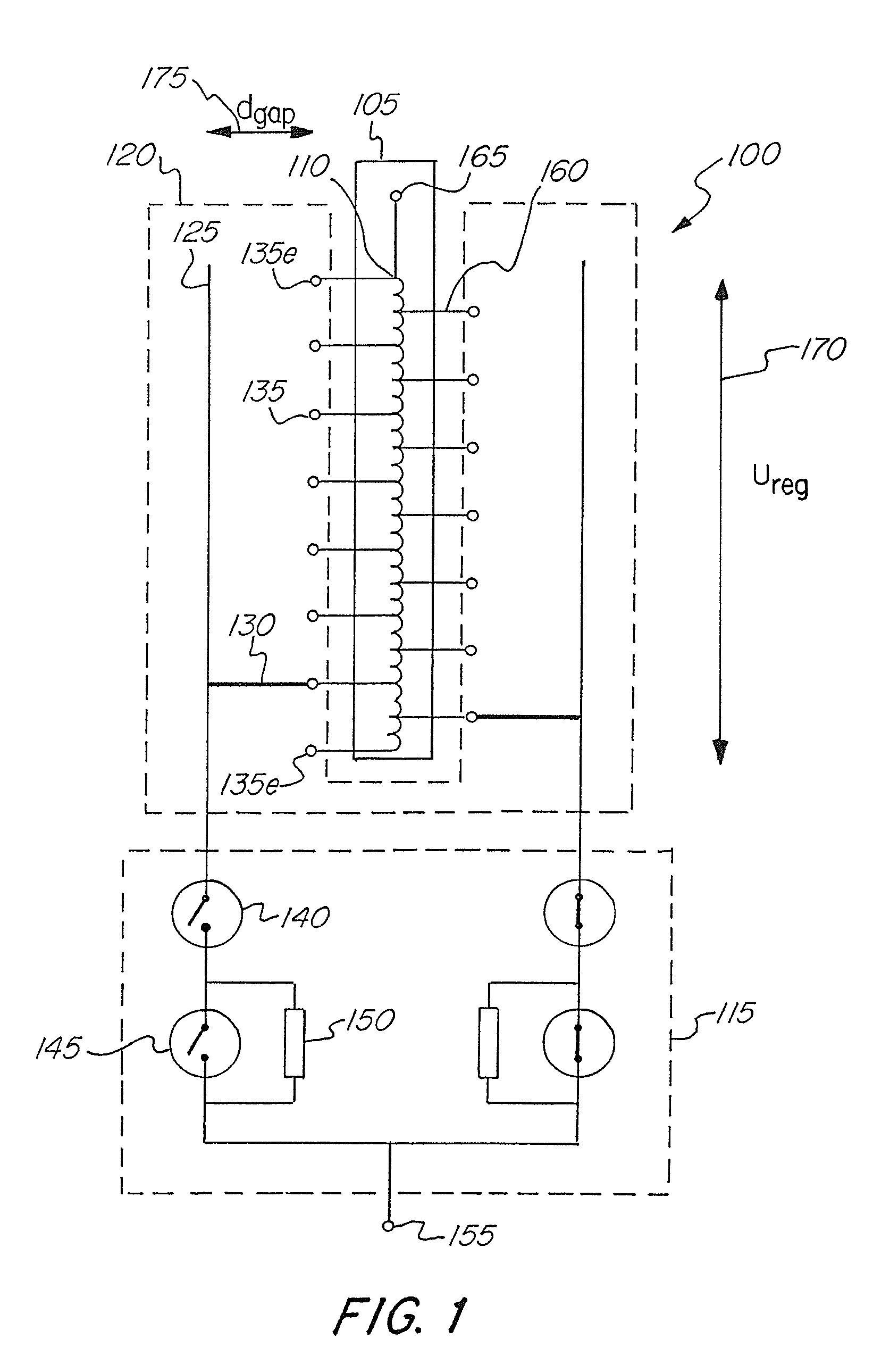
[0047]FIG. 1 schematically illustrates a tap changer 100 of a kind for which the gearbox according to the present invention is intended. The tap changer 100 is connected to a regulating winding 105 of a transformer and has a set of different taps 110. The tap changer of FIG. 1 is of diverter switch type, and comprises a diverter switch 115 and a tap selector 120.

[0048]The tap selector 120 of FIG. 1 comprises two current collectors 125, two selector arms forming two moveable contacts 130 and further comprises a set of fixed contacts 135, where, each fixed contact 135 is arranged to be connected to one of the taps 110 of the regulating winding. The tap changer 100 of FIG. 1 has fifteen different fixed contacts 135, and the regulating winding 105 has fifteen taps 110. The tap changer 100 of FIG. 1 is mechanically linear in the sense that the current collectors 125 are implemented as linear rods, and the fixed contacts 135 are arranged in a linear fashion. The two current collectors 125...


PUM

PropertyMeasurementUnit
angleaaaaaaaaaa
angleaaaaaaaaaa
angleaaaaaaaaaa

Abstract

A gearbox for a tap changer. The gearbox has an input drive shaft arranged to be connected to a motor. The gearbox also has a diverter switch drive output with a diverter shaft. The diverter switch drive output is arranged to be connected for actuation of breakers in a diverter switch of the tap changer. The gearbox further has first and second selector arm drive outputs arranged for actuation of a tap selector of the tap changer. It also has reduction gear means connecting the input drive shaft to the diverter switch drive output and to each of the selector arm drive outputs. Further the gearbox has timing connection means arranged to connect the reduction gear means to each of the selector arm drive outputs. The invention also relates to a tap changer having such a gearbox and to a transformer provided with such a tap changer.

Description

FIELD OF THE INVENTION[0001]The present invention relates to a gearbox for a tap changer, which gearbox has an input drive shaft arranged to be connected to a motor and includes a diverter switch drive output with a diverter shaft, which diverter switch drive output is arranged to be connected for actuation of breakers in a diverter switch of the tap changer.[0002]The invention also relates to a tap changer and to a transformer.BACKGROUND OF THE INVENTION[0003]A tap changer is commonly used in connection with a transformer in order to vary the transformation rate thereof. In a transformer with a tap changer one of the windings in the transformer has a fixed amount of turns connected to the circuit. The other winding has one fixed connection point, whereas the other connection point can be selected among a number of points to attain a required voltage. The selectable points may be located after each other along a portion of the winding corresponding to 70% to 100% of its full extensi...

Claims


Application Information

Patent Timeline
Patent Type & Authority Patents(United States)
IPC IPC(8): F16H57/02H01H3/40H01H19/00H01F21/12H01H3/44H01H9/00F16H1/20F16H27/06H01F29/04
CPCF16H1/20H01H3/40H01H3/44H01H9/0027F16H27/06H01F29/04Y10T74/19642
Inventor MATHAE, JEAN
Owner HITACHI ENERGY LTD
Why Eureka
Try Eureka