
Image display device and method

a technology of image display and image, which is applied in the field of image display device and method, can solve the problem that the image is not disclosed in the technique of reproducing and displaying an image with a natural vision, and achieves the effect of reproducing and displaying an actual photographing scene, and wide dynamic rang

Active Publication Date: 2015-08-25
FUJIFILM CORP
View PDF13 Cites 1 Cited by
  • Summary
  • Abstract
  • Description
  • Claims
  • Application Information

AI Technical Summary

Benefits of technology

[0010]The present invention is made in light of the above-mentioned circumstances, and an object of the present invention is to provide an image display device and method, capable of faithfully reproducing and displaying a photographing scene with a wide dynamic range.
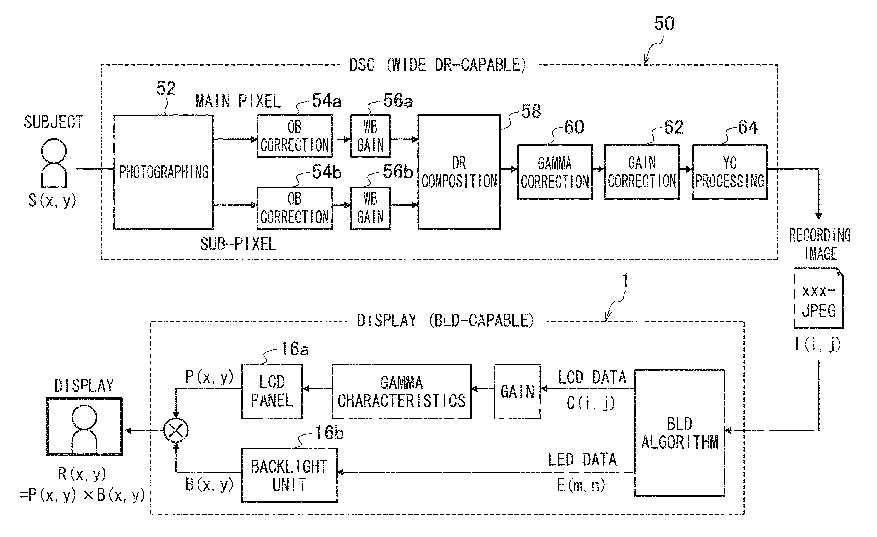
[0012]According to one aspect of the present invention, when the third image with a wide dynamic range formed by compounding the first image and the second image photographed with low sensitivity or low exposure with respect to the first image, the third image having gradation of the high luminance portion suppressed with respect to gradation of the low luminance portion, is displayed in the transmissive type display panel, backlight luminance of each of segments of the backlight unit is individually controlled so that the third image is displayed as an image with a wide dynamic range, that is, the backlight unit is controlled (BLD control) so that the backlight luminance of the segment corresponding to the suppressed high luminance portion in the third image becomes higher than the backlight luminance of the segment corresponding to the low luminance portion in the third image. Accordingly, although the third image is an image with a wide dynamic range in which a high luminance portion is suppressed, luminance of the suppressed high luminance portion is to be extended, thereby enabling a photographing scene corresponding to the third image to be faithfully displayed.
[0027]According to the present invention, an image (third image) in which gradation of the high luminance portion is suppressed with respect to gradation of the low luminance portion is acquired, and the BLD control is performed so that backlight luminance of a segment corresponding to the suppressed high luminance portion becomes higher than the backlight luminance of a segment corresponding to the low luminance portion when the third image is reproduced and displayed. As a result, it is possible to faithfully reproduce and display an actual photographing scene with a wide dynamic range.

Problems solved by technology

Unfortunately, PTL 2 does not disclose a technique of reproducing and displaying an image with a natural vision.

Method used


Image

  • Image display device and method
  • Image display device and method
  • Image display device and method

Examples


Embodiment Construction

[0042]Referring to accompanying drawings, embodiments of the image display device and method in accordance with the present invention will be described.

[0043][Configuration of Image Display Device]

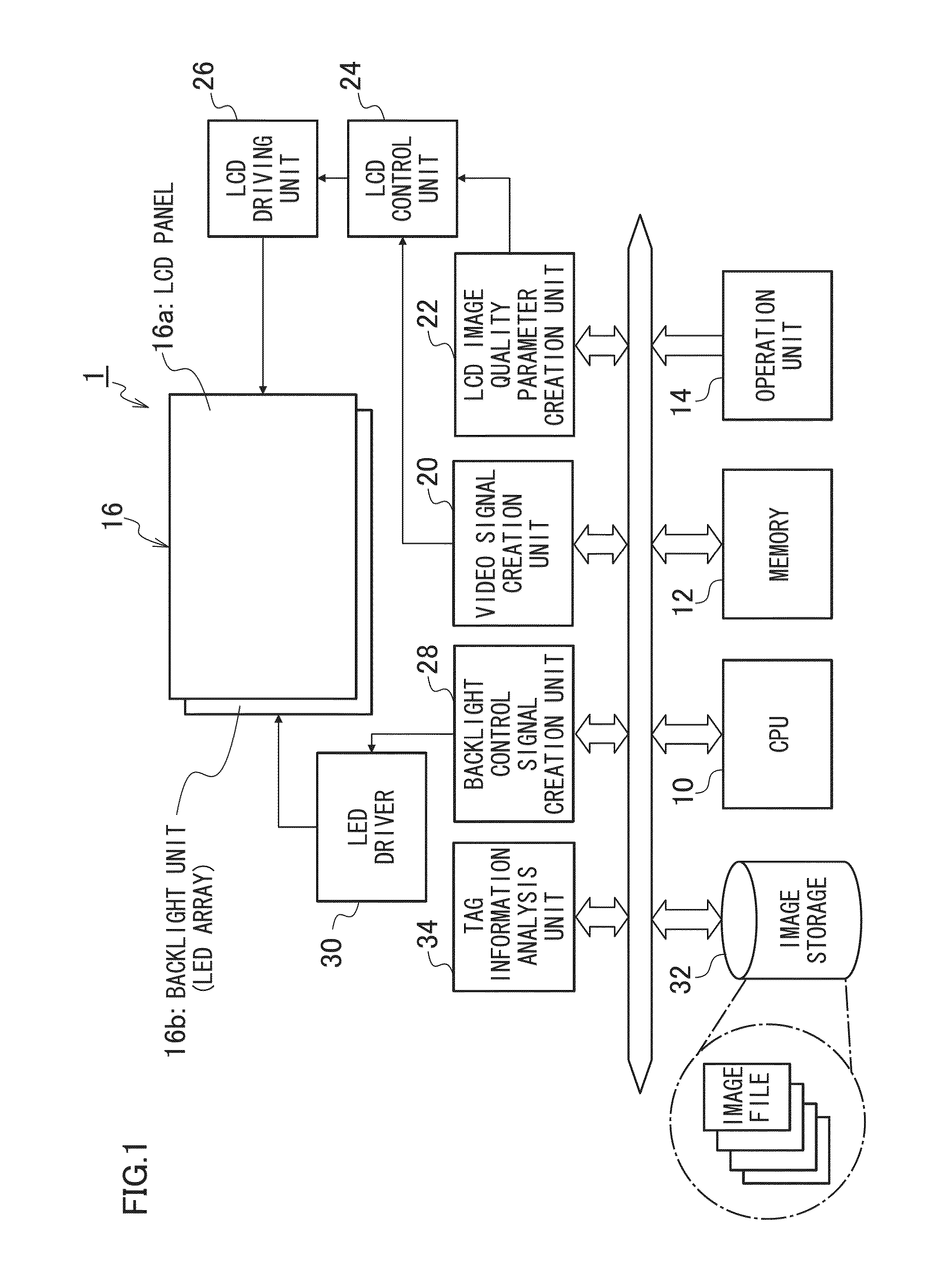
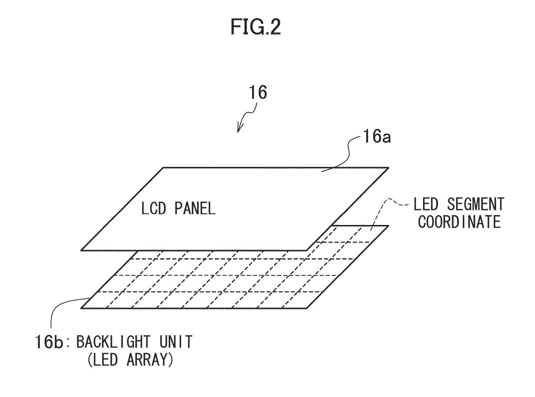
[0044]FIG. 1 is a block diagram showing an embodiment of the image display device in accordance with the present invention, and FIG. 2 is a perspective view of the liquid crystal display unit shown in FIG. 1.

[0045]An image display device 1 shown in FIG. 1 is a display having a backlight local dimming (BLD) function. The image display device 1 shown in FIG. 1 includes: a central processing unit (CPU) 10; a memory 12; an operation unit 14; a liquid crystal display (LCD) 16 (LCD panel 16a (transmissive display panel); a backlight unit (LED array) 16b); a video signal creation unit 20; an LCD image quality parameter creation unit 22; an LCD control unit 24; an LCD driving unit 26; a backlight control signal creation unit 28 (control unit and extract unit); a light emission diode (LED); a drive...


PUM


Abstract

An image display method includes the steps of: acquiring a third image formed by applying dynamic range extension processing to a first image and a second image photographed with low sensitivity or low exposure with respect to the first image, or a fourth image without dynamic range extension processing; displaying the acquired image in a transmissive type display panel; and making backlight luminance of a segment corresponding to a high luminance portion in the third image higher than backlight luminance of a segment corresponding to a low luminance portion when the acquired image is determined to be the third image.

Description

CROSS-REFERENCE TO RELATED APPLICATIONS[0001]This application is a Continuation of PCT International Application No. PCT / JP2013 / 056732 filed on Mar. 12, 2013, which claims priority under 35 U.S.C §119(a) to Japanese Patent Application No. 2012-065738 filed on Mar. 22, 2012. Each of the above applications is hereby expressly incorporated by reference, in their entirety, into the present application.BACKGROUND OF THE INVENTION[0002]1. Field of the Invention[0003]The present invention relates to an image display device and method, and particularly to a technique of controlling backlight luminance of a transmissive display panel.[0004]2. Description of the Related Art[0005]There has been provided a liquid crystal display device having a function (backlight local dimming (BLD) function) of individually controlling a backlight luminance of each of segments of a backlight unit provided in a back face of a liquid crystal panel (Japanese Patent Application Laid-Open No. 2010-097909 (PTL 1))....

Claims


Application Information

Patent Timeline
Patent Type & Authority Patents(United States)
IPC IPC(8): G09G3/34G09G3/20H04N5/235G09G3/36
CPCG09G3/3413G09G3/2092G09G3/3426G09G3/3607G09G3/3648H04N5/2355G09G2320/062G09G2320/066G09G2320/0646G09G2360/16H04N23/741
Inventor WATANABE, MIKIOTAMARU, MASAYA
Owner FUJIFILM CORP
Learn More