
Hammer of a beater mill

a beater mill and hammer technology, applied in the field of hammer of beater mills, can solve the problems of increasing specific power demand, and achieve the effect of optimizing the ability of the impeller head and reducing the dynamic stress of the bolts

Inactive Publication Date: 2015-08-18
GENERAL ELECTRIC TECH GMBH
View PDF29 Cites 2 Cited by
  • Summary
  • Abstract
  • Description
  • Claims
  • Application Information

AI Technical Summary

Benefits of technology

The invention is about improving the lifespan and reducing costs of hammers used in beater mills. The hammer is made up of two parts - the body and the impeller head - which allows for easy replacement of the worn impeller head without having to replace the entire hammer body. This reduces the time and cost of maintenance. The impeller head is securely locked to the hammer body to ensure proper positioning and reduce stress on the bolts and screws. The impeller head also includes a base plate and crushing member, which makes it easy to connect to the hammer body and can be produced at a low cost.

Problems solved by technology

Since coal is rather abrasive, the head of the hammer that changes this form and size due to abrasion leading to an increasing specific power demand.

Method used


Image

  • Hammer of a beater mill
  • Hammer of a beater mill
  • Hammer of a beater mill

Examples


first embodiment

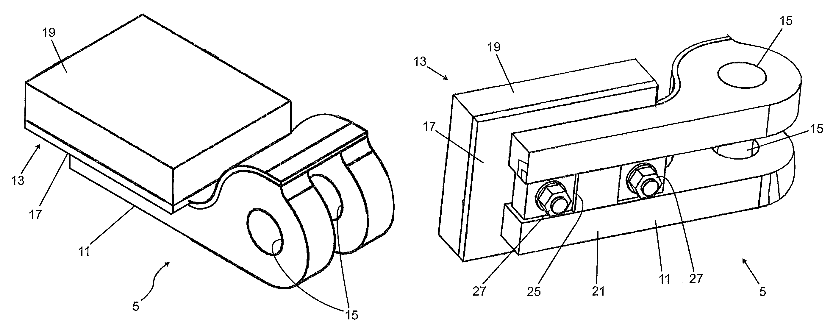
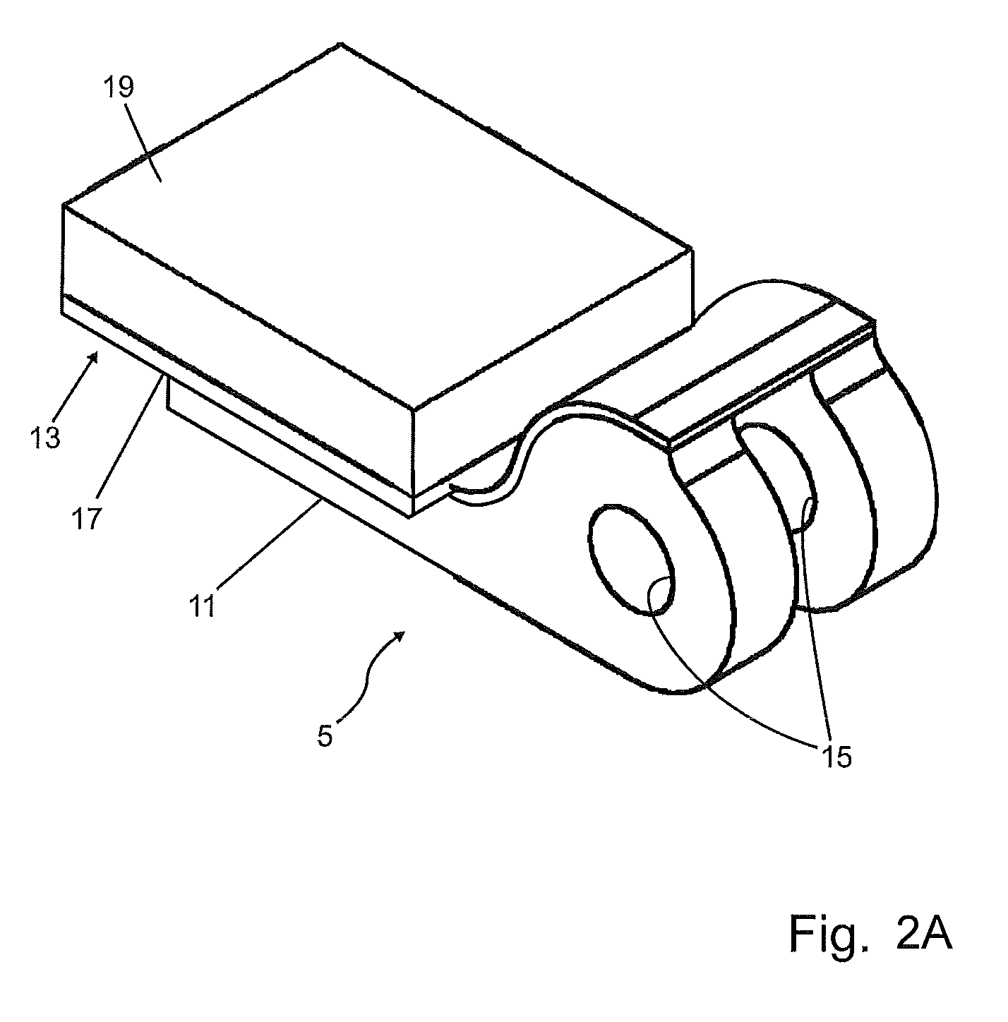
[0029]FIGS. 2A and 2B show perspective views of the claimed hammer according to the invention.

[0030]FIG. 2C shows a longitudinal section of the first embodiment of the claimed hammer 5.

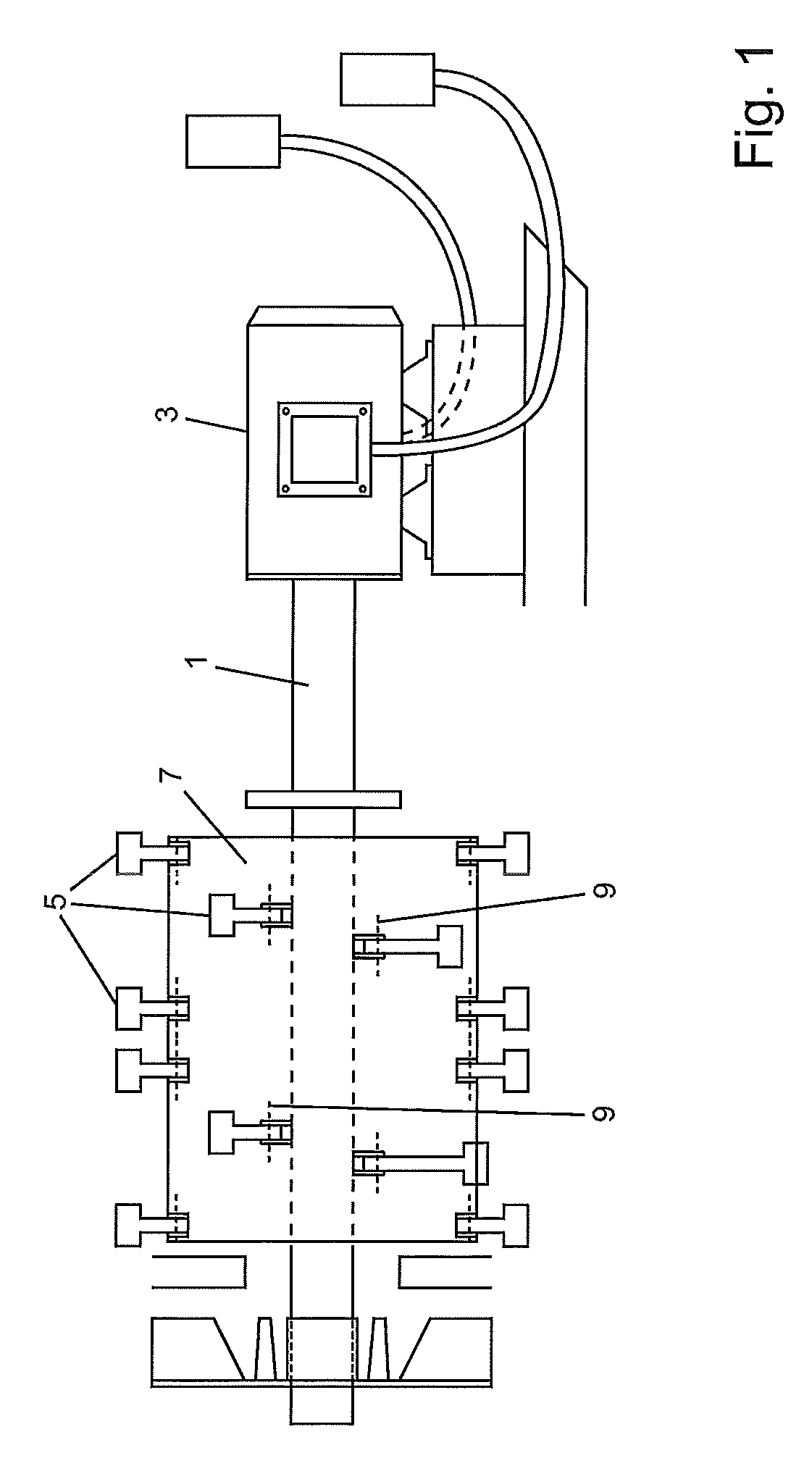
[0031]As can best be seen from FIG. 2B the hammer 5 comprises a hammer body 11. At a first end of this hammer body 11 an impeller head 13 is mounted. At the opposite end of the hammer body 11 a bore 15 or perforation is comprised. The bore 15 is the fixing means to connect the hammer 5 with the drum 7 of the rotor 1 as can be seen from FIG. 1.

[0032]As can be seen from the FIG. 2B the impeller head 13 comprises a base plate 17 and a crushing member 19. The crushing member 19 may be made of ceramics. In any case it has to be made of a material that is highly resistant against abrasive wear. The abrasion of the crushing member 19 depends on the material to be crushed. Due to the interaction between the material to be crushed and the material of the crushing means the decision for a material for the crush...

second embodiment

[0042]In FIGS. 3A-3D the claimed invention is shown.

[0043]The same parts have the same reference numerals as in FIGS. 2A-2C. The main difference between the first and the second embodiments concerns the positively locking of the impeller head 13 and the hammer body 11. As can best be seen from FIG. 3C the base plate 17 comprises a protrusion 21 and one bolt 23.

[0044]The protrusion 21 has on the left side on FIG. 3C a triangular key 33. At the first end of the hammer body 11 a slot 35 with a complementary cross section is comprised. This key and slot connection 33 and 35 very effectively transfers the centrifugal forces between the impeller head 13 and the hammer body 11 and centers the impeller head 13 using the centrifugal forces.

[0045]To make sure that the key and slot connection 33 and 35 remain engaged during operation of the beater mill, the hammer body 11 comprises a second protrusion 31 with a slot 39 for the bolt 23.

[0046]The slot 39 is chamfered at one end and interacts wit...


PUM


Abstract

A hammer (5) for a beater mill used to process coal, biomass material and other materials is provided having a hammer body (11), an impeller head (13) at a first end of the hammer body (11), and a bore (15) at a second opposite end of the hammer body (11). The impeller head (13) is detachably connected to the hammer body (11) by a base plate 17. Base plate (17) has a first side with a protrusion (21) and at least one bolt (29) protruding therefrom and a second opposed planar side with a crushing member (19). Protrusion (21) and at least one bolt (29) detachably connects impeller head (13) to first end of hammer body (11).

Description

BRIEF DESCRIPTION[0001]Beater mills comprising a rotor and several hammers are often used to process coal, biomass material and other materials.[0002]Examples for this type of beater mills are for example known from EP 2 359 934 A2 or EP 1 028 808 B1.[0003]Beater mills comprise a rotor and a casing. Several hammers are bolted to the rotor. During operation, the rotor drives the hammer, which crushes, for example, coal to reduce its grain size. Since coal is rather abrasive, the head of the hammer that changes this form and size due to abrasion leading to an increasing specific power demand.[0004]Once the hammers have reached a certain abrasion they need to be changed. For this reason the hammers are bolted to the rotor by means of a bolt and a nut for example.[0005]To extend the time intervals before changing the hammers, it is known to cast or forge the hammers of a material with a great resistance against abrasion. These materials are rather expensive and difficult to machine. A s...

Claims


Application Information

Patent Timeline
Patent Type & Authority Patents(United States)
IPC IPC(8): B02C13/00B02C13/28B02C13/26B02C13/04
CPCB02C13/28B02C13/04B02C13/26
Inventor STEGELITZ, PETER
Owner GENERAL ELECTRIC TECH GMBH
Learn More