Display device
a display device and display technology, applied in the field of display devices, can solve the problems of increasing the cost of rotation and arrangement of the unit optical elements, the inability to control the output of the unit optical element, so as to achieve the effect of reliably preventing the generation of virtual images
- Summary
- Abstract
- Description
- Claims
- Application Information
AI Technical Summary
Benefits of technology
Problems solved by technology
Method used
Image
Examples
first embodiment
[0047]As below, the first embodiment of the invention will be explained using FIGS. 1 to 14.
[0048]A display device of the embodiment is an example of a display device that may generate a planar image in a space.
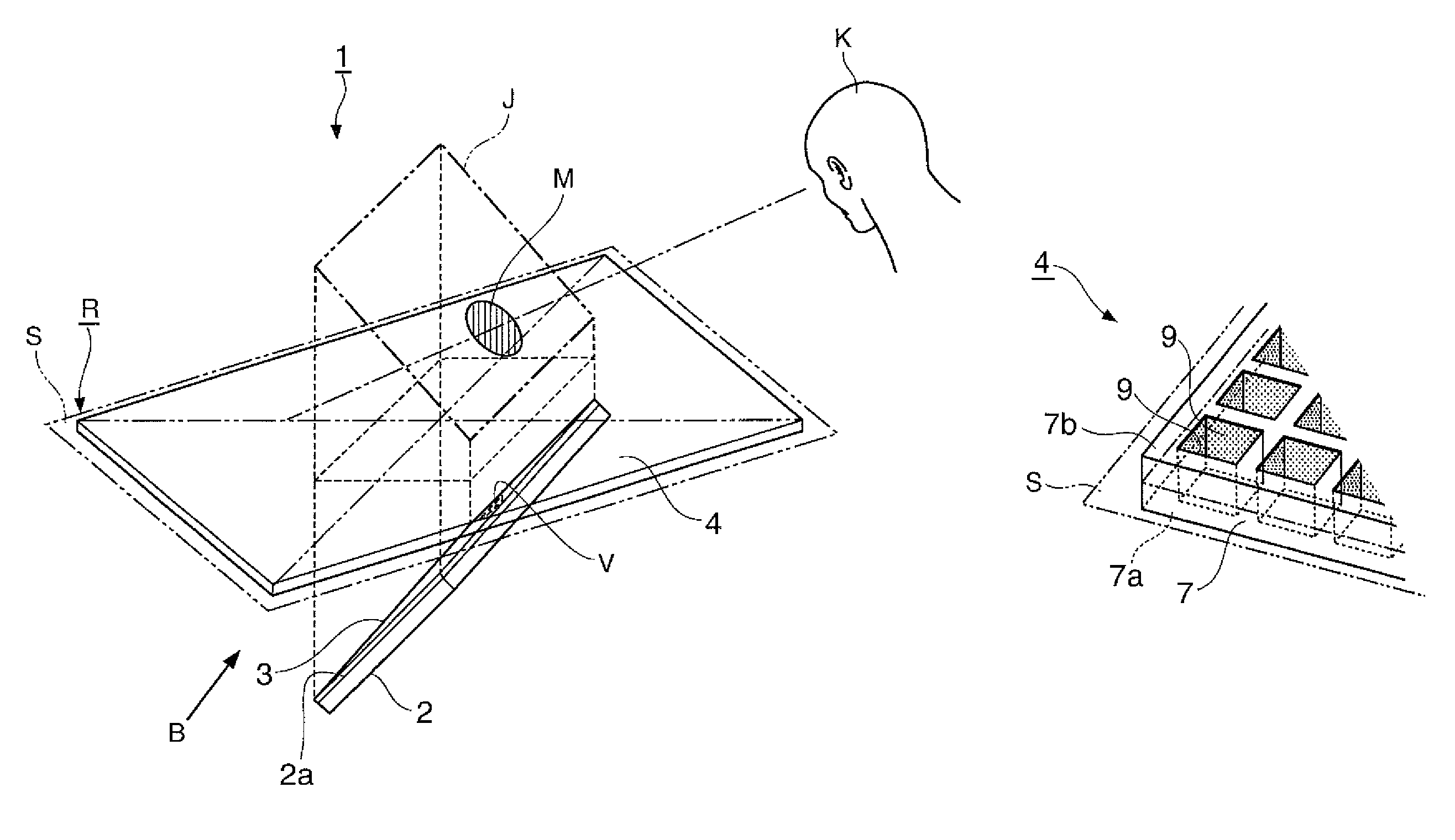
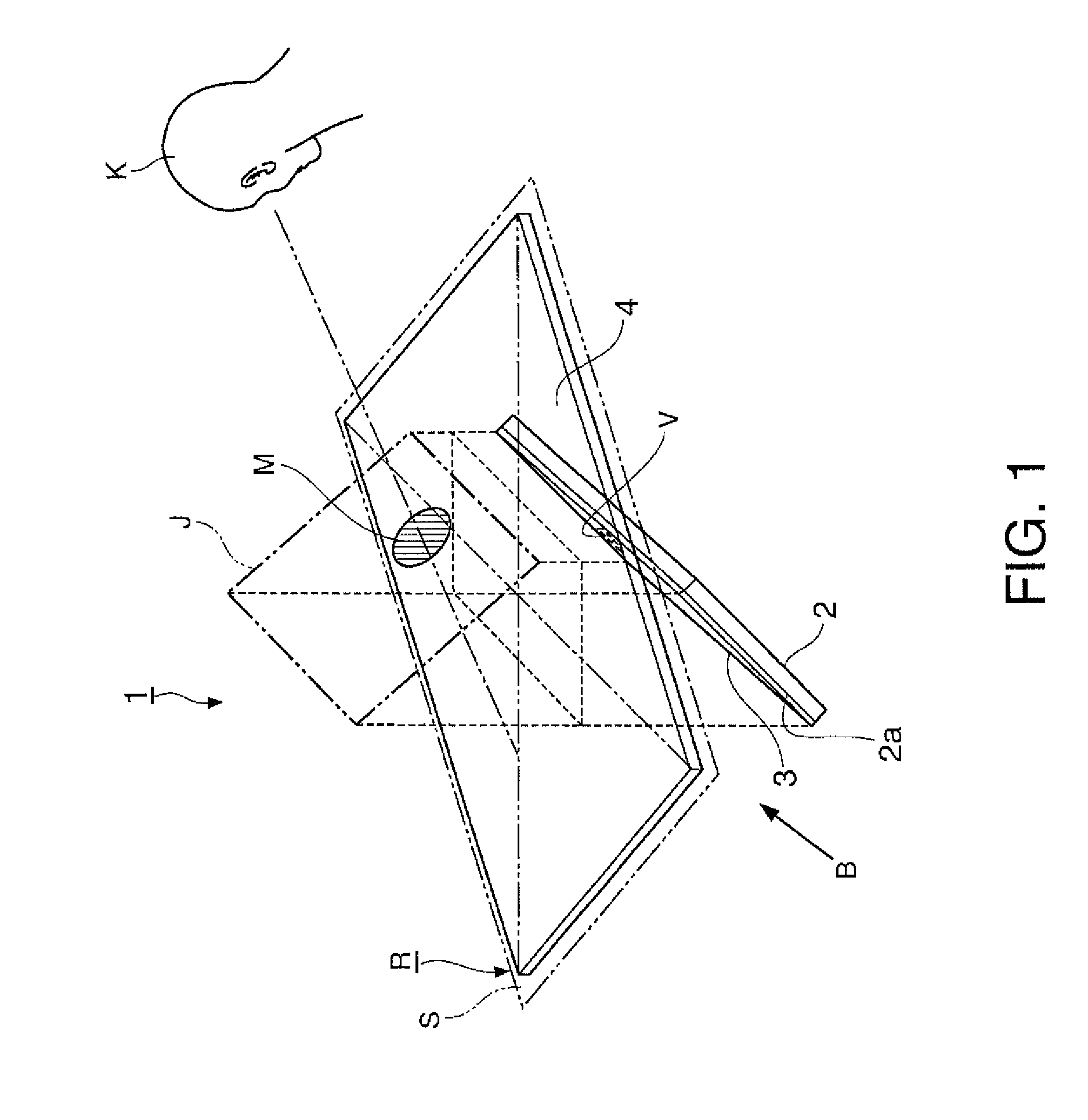
[0049]FIG. 1 is a perspective view showing a schematic configuration of the display device of the embodiment.
[0050]Note that, in all of the following drawings, the scale of dimensions may be made different depending on component elements for facilitating visualization of the respective component elements.
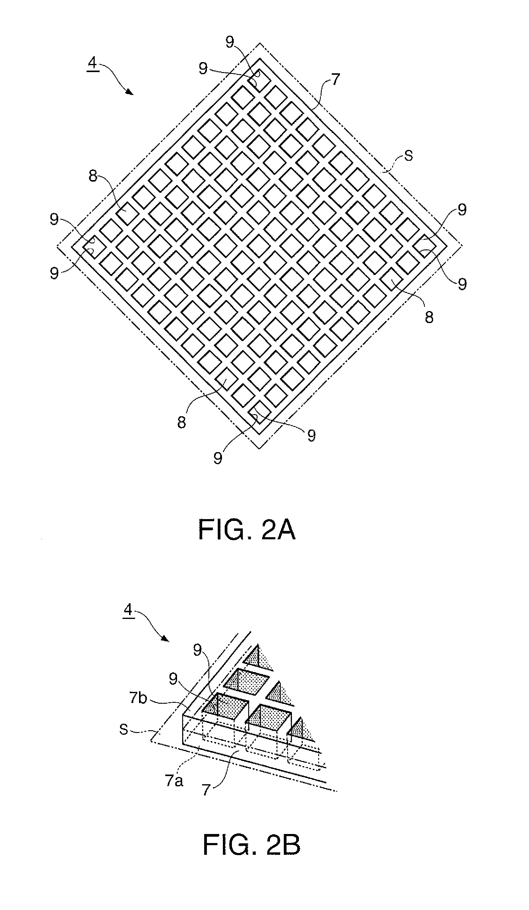
[0051]As shown in FIG. 1, the display device 1 of the embodiment includes a flat panel display 2 (object image generator), a diffusion angle limiting film 3 (diffusion angle limiting member), and a retrotransmissive material 4 (imaging element). In the following explanation, the flat panel display 2 will be abbreviated to FPD. The FPD 2 displays characters and images on an image display surface 2a (image generation surface) based on image signals input from the outside. In th...
second embodiment
[0095]The second embodiment of the invention will be explained using FIGS. 15 and 16.
[0096]The basic configuration of a display device of the embodiment is the same as that of the first embodiment, and the configuration of the object image generator is different from that of the first embodiment.
[0097]FIG. 15 is a perspective view showing a schematic configuration of the display device of the embodiment. FIG. 16 is a sectional view of a screen and a diffusion angle limiting film used for the display device of the embodiment.
[0098]In FIGS. 15 and 16, the common component elements to those in the drawings of the first embodiment have the same signs and their explanation will be omitted.
[0099]As shown in FIG. 15, the display device 21 of the embodiment includes a projection system 22 (object image generator), the diffusion angle limiting film 3 (diffusion angle limiting member), and the retrotransmissive material 4 (imaging element). The projection system 22 includes a transmissive scr...
third embodiment
[0102]As below, the third embodiment of the invention will be explained using FIGS. 17 to 19.
[0103]A display device of the embodiment is the same as the second embodiment in that the object image generator includes the screen and the projector, and different from the second embodiment in the configuration of the diffusion angle limiting member.
[0104]FIG. 17 is a perspective view showing a schematic configuration of the display device of the embodiment. FIG. 18 is a sectional view of a screen assembly used for the display device of the embodiment.
[0105]In FIGS. 17 and 18, the common component elements to those in the drawings of the second embodiment have the same signs and their explanation will be omitted.
[0106]As shown in FIG. 17, the display device 31 of the embodiment includes a projection system 32 (object image generator) and the retrotransmissive material 4 (imaging element). The projection system 32 includes a screen assembly 33 and a projector 34 that projects an image on t...
PUM
 Abstract
Description
Claims
Application Information
 - R&D
- Intellectual Property
- Life Sciences
- Materials
- Tech Scout
- Unparalleled Data Quality
- Higher Quality Content
- 60% Fewer Hallucinations
Browse by: Latest US Patents, China's latest patents, Technical Efficacy Thesaurus, Application Domain, Technology Topic, Popular Technical Reports.
© 2025 PatSnap. All rights reserved.Legal|Privacy policy|Modern Slavery Act Transparency Statement|Sitemap|About US| Contact US: help@patsnap.com


