Eureka AIR delivers breakthrough ideas for toughest innovation challenges, trusted by R&D personnel around the world.

Volume rendering a graphical 3D scene containing a 3D volumetric object and atmospheric effects

a volumetric object and atmospheric effect technology, applied in the field of polygon-based graphics systems, can solve the problems of unrealistic cues, affecting training, and not always working well in polygon-based graphics systems for other volumetric obscurants

Active Publication Date: 2015-07-28
ROCKWELL COLLINS INC
View PDF7 Cites 4 Cited by
  • Summary
  • Abstract
  • Description
  • Claims
  • Application Information

AI Technical Summary

Benefits of technology

The invention relates to a computerized method and system for rendering a graphical image containing a volumetric object on an electronic display. The method involves defining the volumetric object as a volume comprising a plurality of polygons, and then rendering the volume for a first plurality of pixels of the electronic display. A graphical image is then rendered for a second plurality of pixels of the display, which is described by different characteristics. When a view ray for one of the second plurality of pixels intersects with one of the first plurality of pixels, the global characteristics and a proportion of the volume characteristics are combined to create the graphical image. The proportion is defined by the extent of the intersection of the view ray. The technical effect of the invention is to provide an improved method and system for creating graphical images that include volumetric objects, which results in more realistic and detailed images.

Problems solved by technology

Simulating weather effects (e.g., a rain squall underneath a heavy cloud layer) is challenging with traditional polygon-based graphics systems.
Also, polygon-based graphics systems do not always work well for other volumetric obscurants such as dust, smoke, clouds, and fog.
Simulation of regional weather effects has been a long-term challenge for flight simulation.
For example, in a flight simulation system, if a pilot flies through a cloud, the polygonal construct often provides unrealistic cues which may negatively impact training.
This technique may have less-than-satisfactory results.
As the global fog density is increased, it reduces the clarity of the entire scene—not just that which lies within the rain squall.
This may lead to false visual cues which may negatively impact training value.

Method used


Image

  • Volume rendering a graphical 3D scene containing a 3D volumetric object and atmospheric effects
  • Volume rendering a graphical 3D scene containing a 3D volumetric object and atmospheric effects
  • Volume rendering a graphical 3D scene containing a 3D volumetric object and atmospheric effects

Examples


Embodiment Construction

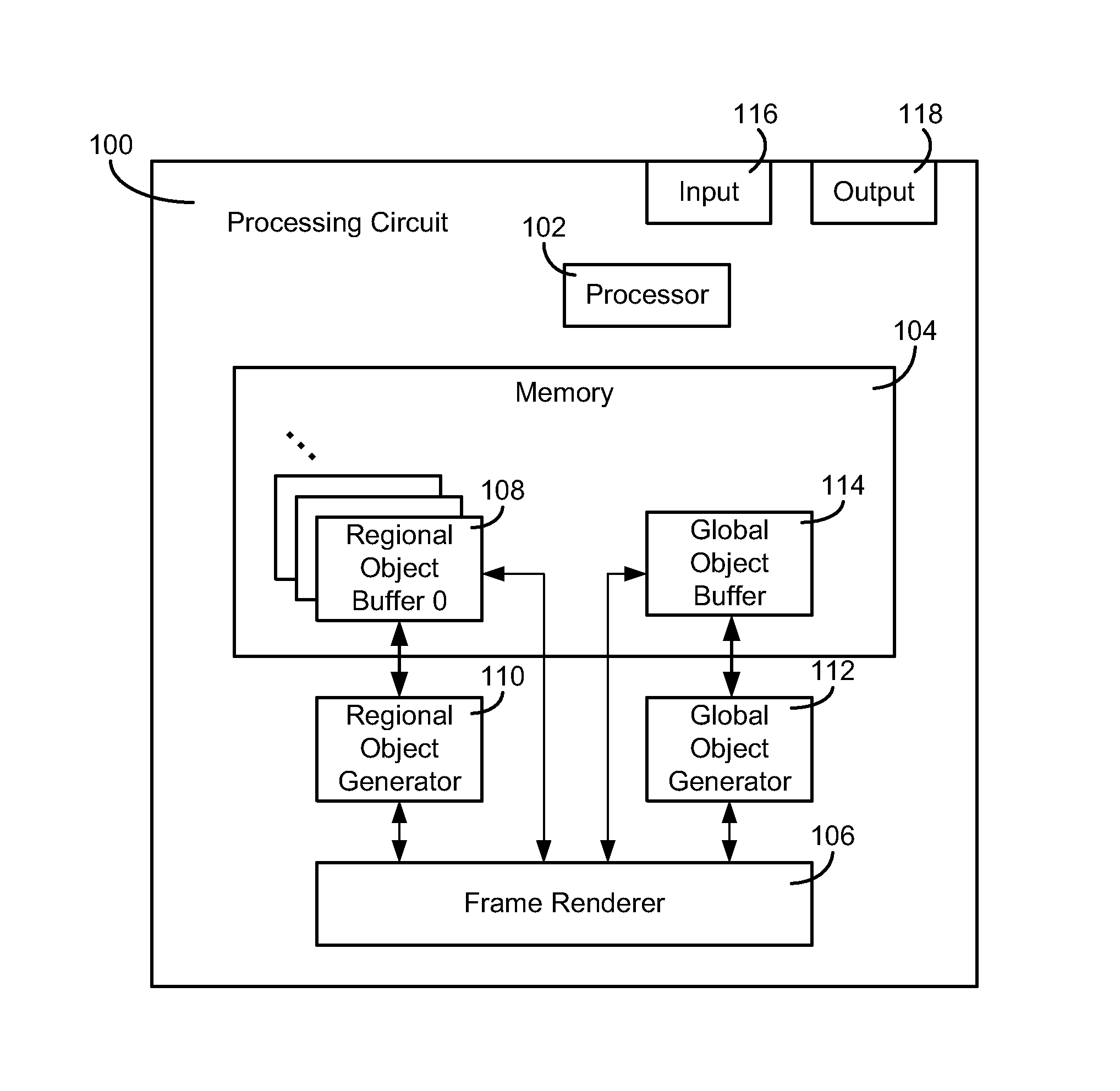
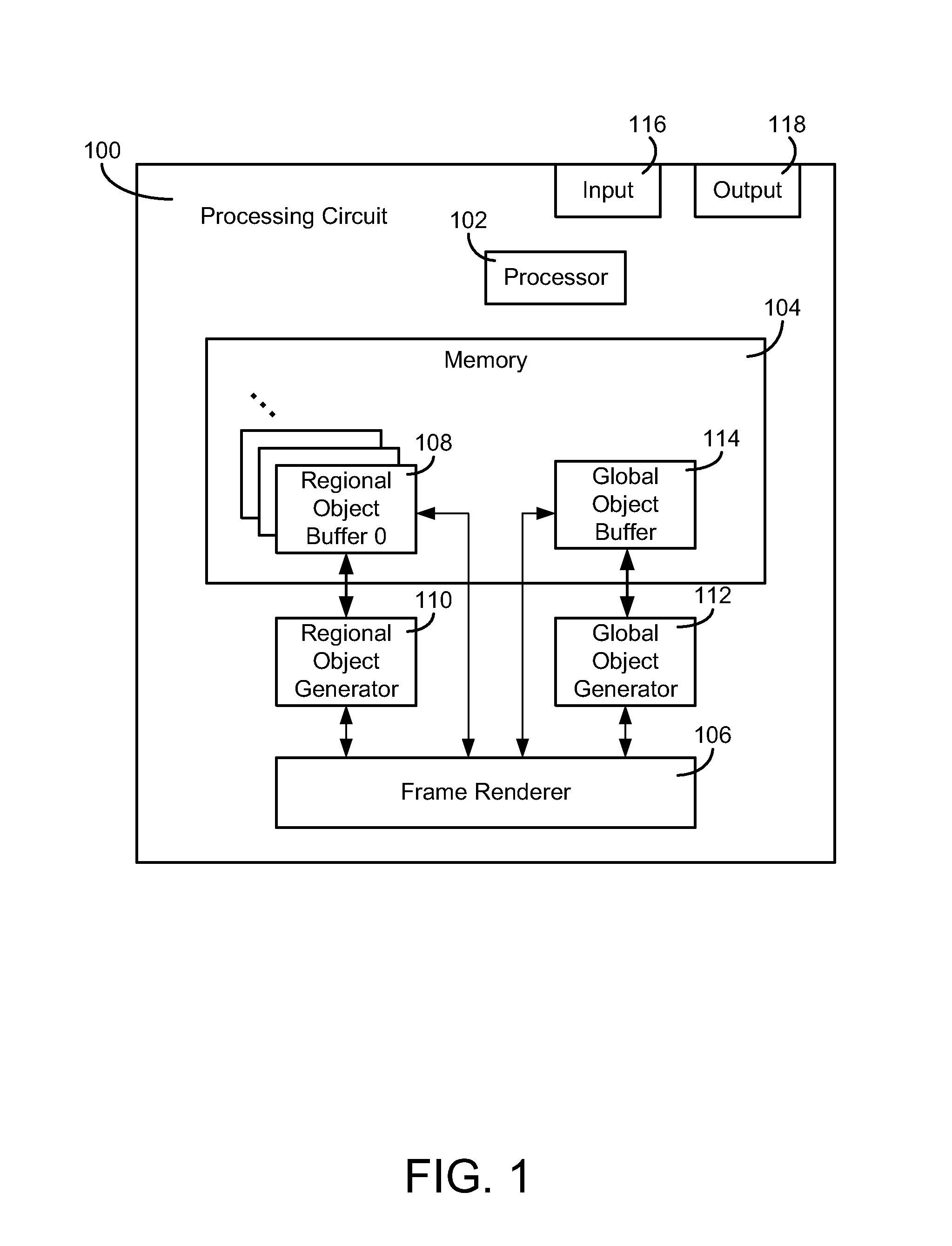
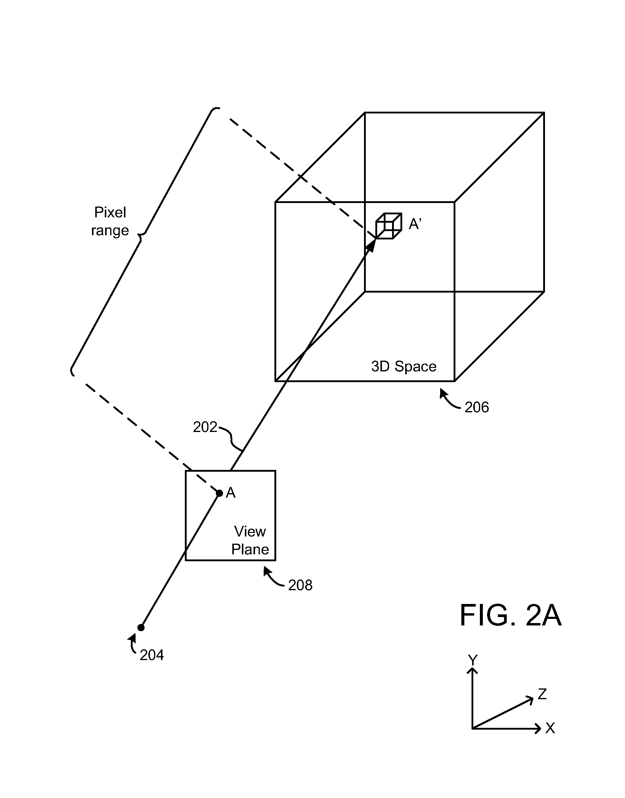
[0022]In one or more embodiments of the present disclosure, polygon-based volumes are implemented for display in frames on a display device depicting visual scenes. This may advantageously enable a modeler to define the volume's overall shape and appearance. In one or more embodiments, the volume may be modeled as a set of polygons that define a convex hull. The convex hull may have an exterior surface and an interior surface. In one or more embodiments, the volume may be used advantageously to simulate multiple volumetric-type obscurants, e.g., fog, dust, smoke, trees, bushes, etc. In one or more embodiments, the volume-defining polygons use characteristics (e.g., texture, color, etc.) to control the visual appearance of the outside and / or inside of the volume.

[0023]In one or more embodiments, as the volume-defining polygons are rendered, the attributes for each pixel are recorded in dedicated volume buffers. The buffers may store the distance to the front of the volume (entry) for...


PUM


Abstract

A computerized method and system of rendering a graphical image containing a volumetric object on an electronic display is provided. The method includes defining, at a processing circuit, the volumetric object as a volume. The volume comprises a plurality of polygons. The method includes rendering the volume for a first plurality of pixels of the electronic display. The volume is described by volume characteristics. The method includes rendering a graphical image for a second plurality of pixels of the electronic display. The graphical image is described by global characteristics. When a view ray for at least one of the second plurality of pixels intersects at least one of the first plurality of pixels, the global characteristics and a proportion of the volume characteristics are combined when rendering the graphical image. The proportion is defined by an extent of the intersection of the view ray.

Description

BACKGROUND OF THE INVENTION[0001]Simulating weather effects (e.g., a rain squall underneath a heavy cloud layer) is challenging with traditional polygon-based graphics systems. Also, polygon-based graphics systems do not always work well for other volumetric obscurants such as dust, smoke, clouds, and fog. Simulation of regional weather effects has been a long-term challenge for flight simulation.[0002]For example, in a flight simulation system, if a pilot flies through a cloud, the polygonal construct often provides unrealistic cues which may negatively impact training. For example, a rain squall may be modeled with a set of textured polygons. As the pilot flies into the squall, the run-time software could decrease the visibility of the scene to simulate the fact that the pilot is now inside a region of lower visibility. This technique may have less-than-satisfactory results. As the global fog density is increased, it reduces the clarity of the entire scene—not just that which lies...

Claims


Application Information

Patent Timeline
Patent Type & Authority Patents(United States)
IPC IPC(8): G06T17/00G06T19/00
CPCG06T17/00G06T19/00G06T13/60G06T15/06G06T15/40
Inventor GARDINER, HAROLD DEESKOWYRA, THOMAS PETERFITZGERALD, RAYMOND LEETHORUP, SETH JOHN
Owner ROCKWELL COLLINS INC
Why Eureka
Eureka Blog
Learn More