Back pressure valve

a valve body and back pressure technology, applied in the field of valves, can solve the problems of high pressure differential, inability to respond to pressure, and valve components tend to wear faster

Inactive Publication Date: 2015-07-14
FLOMATIC CORP
View PDF13 Cites 4 Cited by
  • Summary
  • Abstract
  • Description
  • Claims
  • Application Information

AI Technical Summary

Problems solved by technology

However, a high pressure differential is required to operate conventional back pressure valve to overcome the force from the spring that biases the valve in the closed position.
As a result, conventional back pressure are not responsive to small changes in pressure and the valve components tend to wear faster.

Method used


Image

  • Back pressure valve
  • Back pressure valve
  • Back pressure valve

Examples


Embodiment Construction

[0012]For the purposes of promoting an understanding of the principles of a valve designed and constructed in accordance with one or more aspects of the present invention, reference will now be made to the embodiments, or examples, illustrated in the drawings and specific language will be used to describe these. It will nevertheless be understood that no limitation of the scope of the invention is thereby intended. Any alterations and further modifications in the described embodiments, and any further applications of the principles of the invention as described herein are contemplated as would normally occur to one skilled in the art to which the back pressure valve relates.

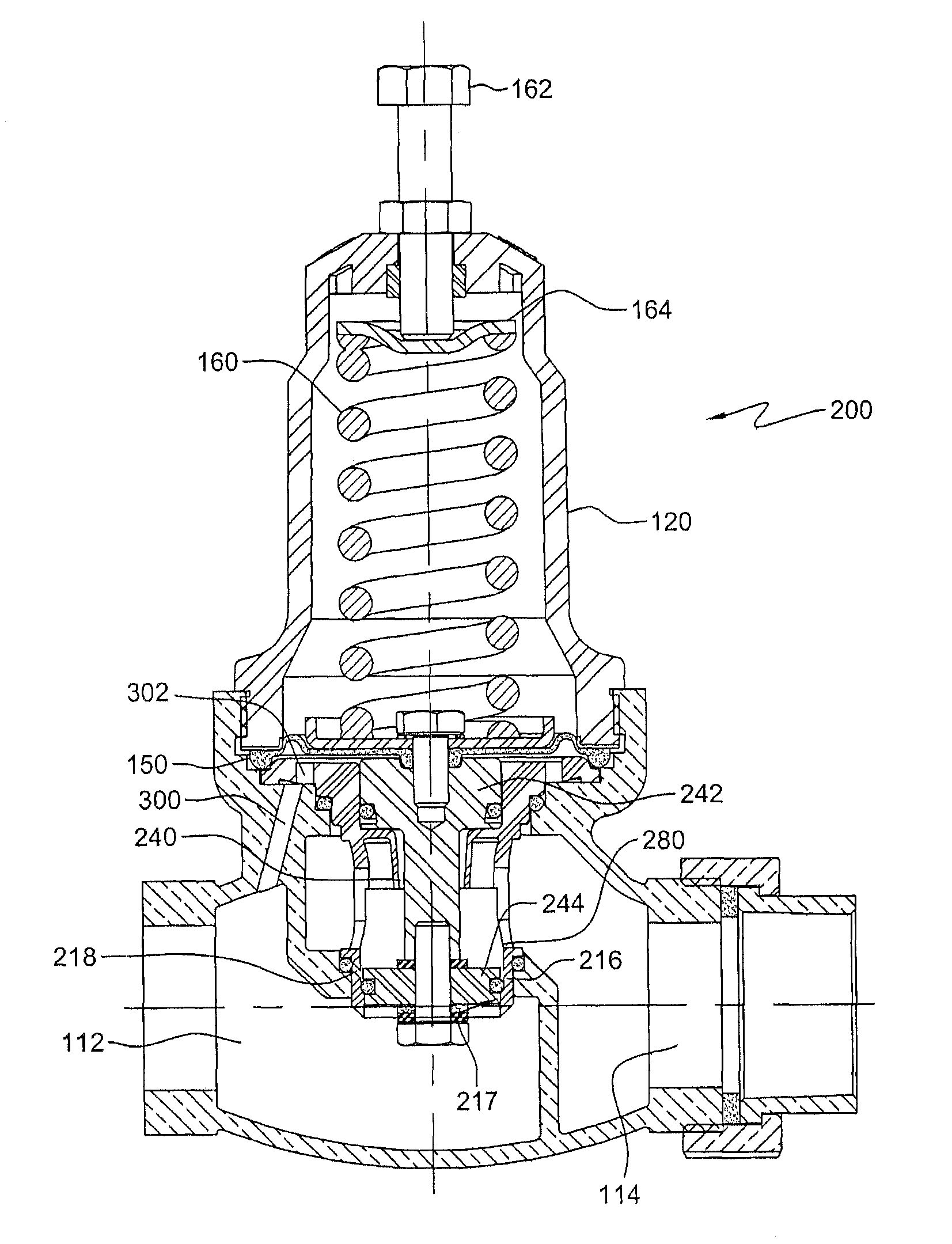
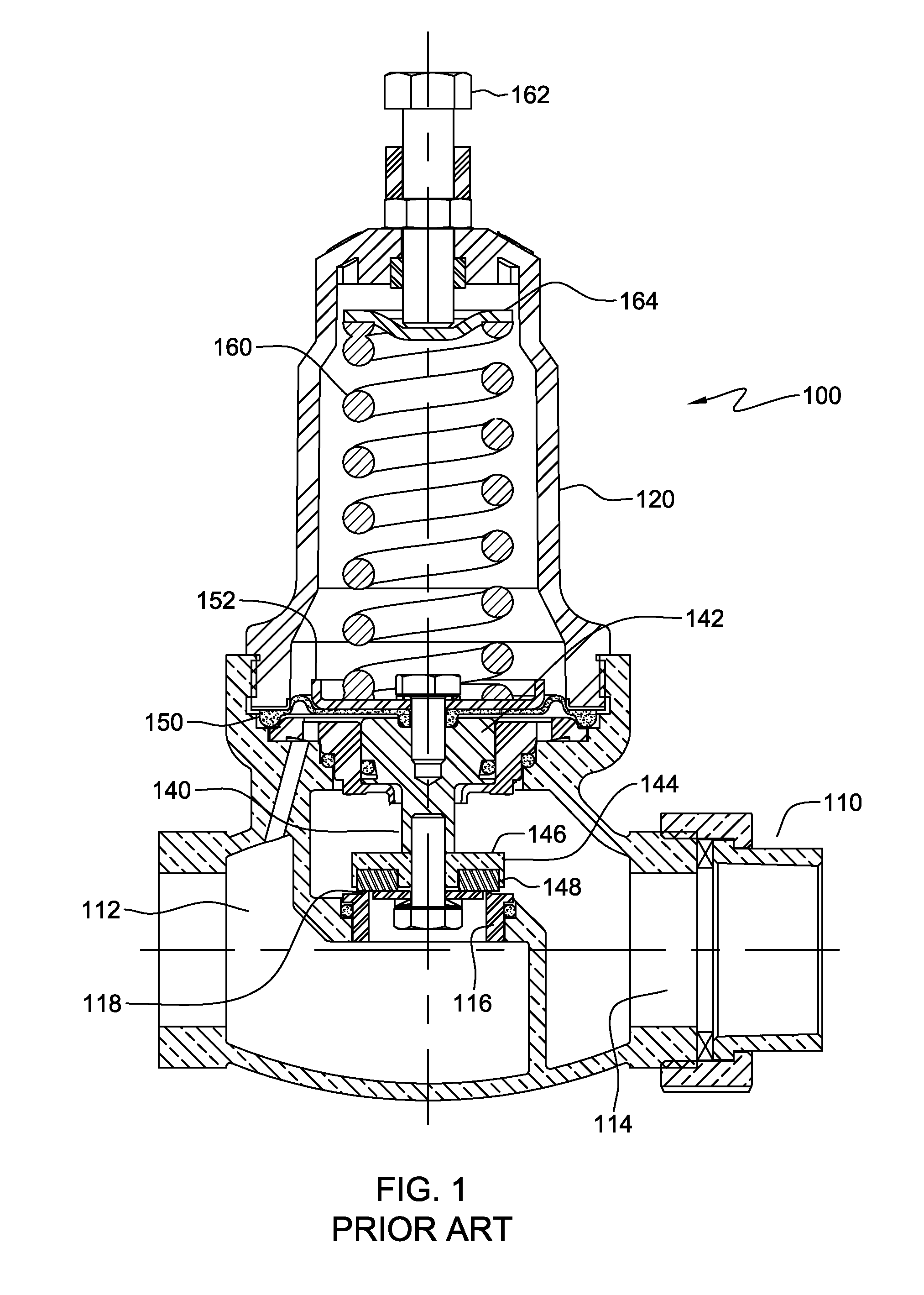
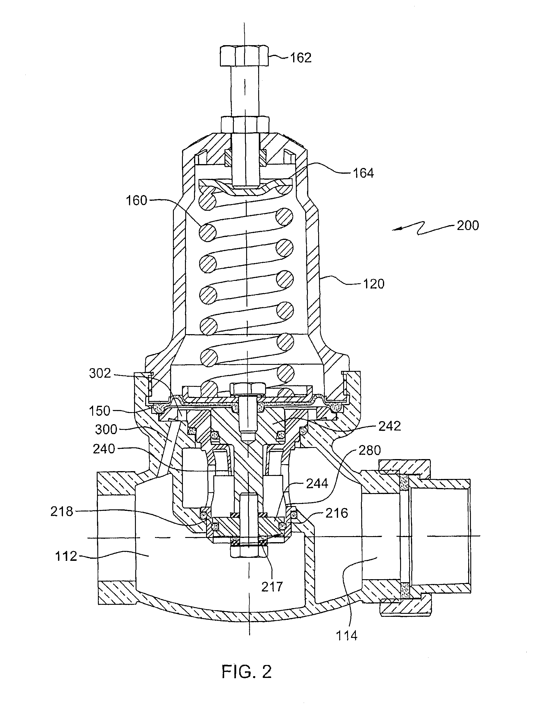
[0013]FIG. 1 illustrates a conventional back pressure valve 100. As illustrated in FIG. 1, a conventional back pressure valve 100 has a pressure regulator housing 110, a pressure controller housing 120 and a flexible diaphragm 150 disposed between pressure controller housing 120 and pressure regulator housing 110...


PUM


Abstract

A back pressure valve comprises a pressure regulator housing affixed to a pressure controller housing and a diaphragm disposed between the pressure regulator housing and the pressure controller housing. In one aspect, the back pressure valve includes a valve member moveable between a fully open position and a fully closed position. The pressure regulator housing includes an inlet chamber communicating with an outlet chamber through at least one fluid passage in a sleeve. The valve member includes a stem connected to a valve head. The valve head includes an outer surface that is received and guided during movement by an inner surface of the sleeve. Upper and lower outer surface of the valve head provide stability to the valve member during opening and closing of the back pressure valve.

Description

BACKGROUND[0001]This invention relates generally to the field of valves, and more specifically to back pressure valves.BRIEF SUMMARY[0002]Back pressure valves are designed to regulate a minimum pre-set upstream or inlet pressure to an un-regulated downstream or outlet pressure regardless of water flow. Conventional back pressure valves have a valve that comprises a flexible diaphragm that is resiliently urged against a valve seat. Diaphragm back pressure valves apply positive discharge pressure to a pump system to prevent siphoning and eliminate varying dosage rates caused by fluctuating downstream pressure. The diaphragm is held against a valve seat by the force of an internal spring. When the preset pressure is exceeded, the diaphragm is forced up and system fluid flows through the valve to the injection point. However, a high pressure differential is required to operate conventional back pressure valve to overcome the force from the spring that biases the valve in the closed posi...

Claims


Application Information

Patent Timeline
Patent Type & Authority Patents(United States)
IPC IPC(8): F16K31/12G05D16/06
CPCG05D16/0658Y10T137/7793G05D16/024
Inventor ANDERSSON, ALLAN BO
Owner FLOMATIC CORP
Why Eureka
Try Eureka