Method and apparatus for mounting solar panels

a solar panel and mounting method technology, applied in the direction of machine supports, heat collector mounting/supports, light and heating apparatus, etc., can solve the problem that no specific feature is adequately provided, and achieve the effect of more flexibility

Active Publication Date: 2015-07-14
IRONRIDGE
View PDF237 Cites 73 Cited by
  • Summary
  • Abstract
  • Description
  • Claims
  • Application Information

AI Technical Summary

Benefits of technology

[0005]Panel supports attach to the edge of the panels and also attach to the roof mounts. The roof mount attachment to the panel supports can be adjusted in height to allow for uneven roofs. The panel supports can be attached anywhere along the edge of the solar panel including along two adjacent solar panels. This allows for adjustment in the horizontal direction and which allows for easy attachment to any of the roof rafters. The roof mounts are adjustable in the up / down direction of the roof. These adjustments allow for adjustment in all three dimensions which allows more flexibility in the location of the solar panels on the roof.

Problems solved by technology

Solar panel mounting systems have provided a number of features, however none has adequately provided specific features and adequately combined features that make an economical, easy to install system as now provided that allows adequate grounding, provides installation ease, and universal application to a great variety of solar panel manufactures as the present system.

Method used


Image

  • Method and apparatus for mounting solar panels
  • Method and apparatus for mounting solar panels
  • Method and apparatus for mounting solar panels

Examples


Embodiment Construction

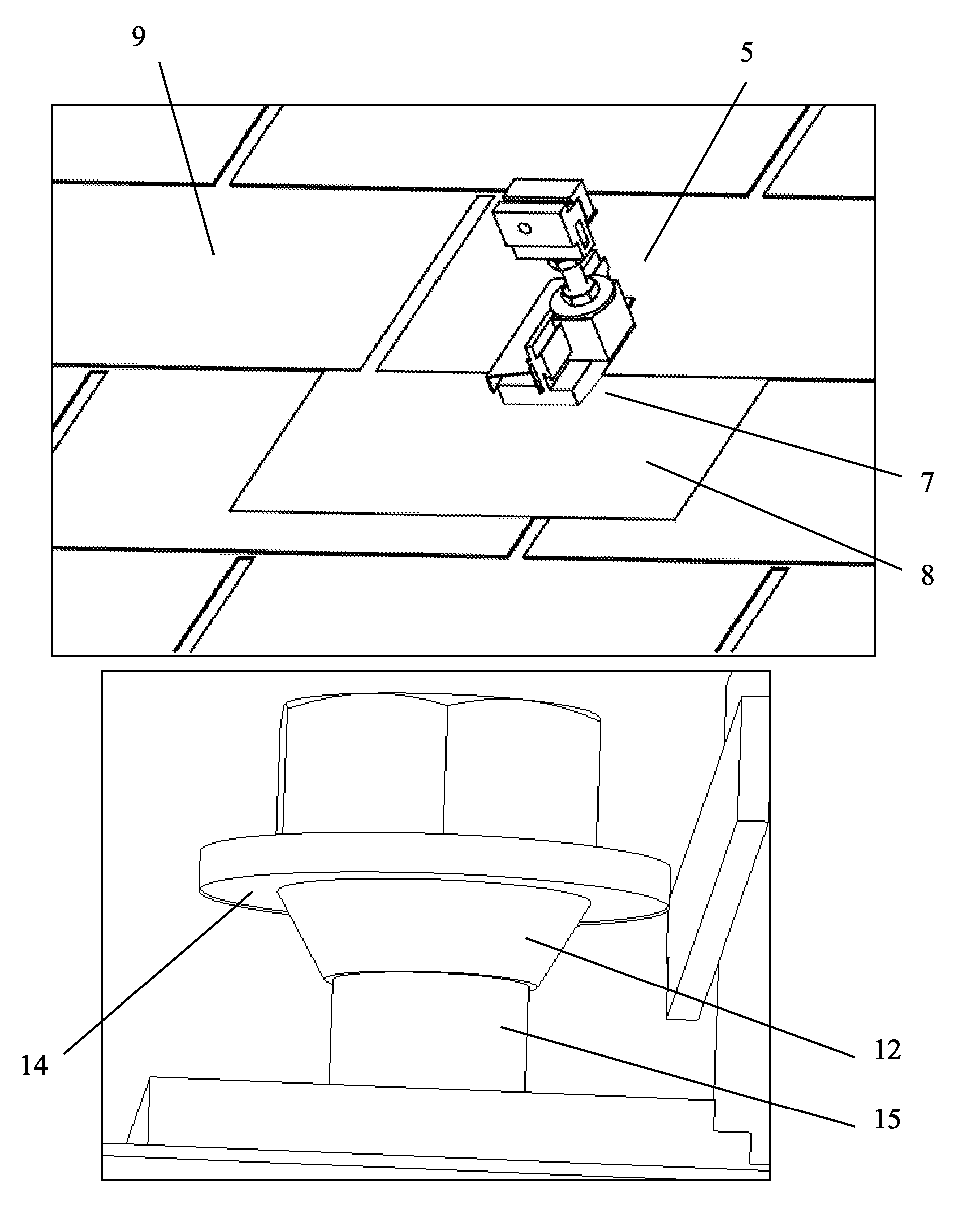
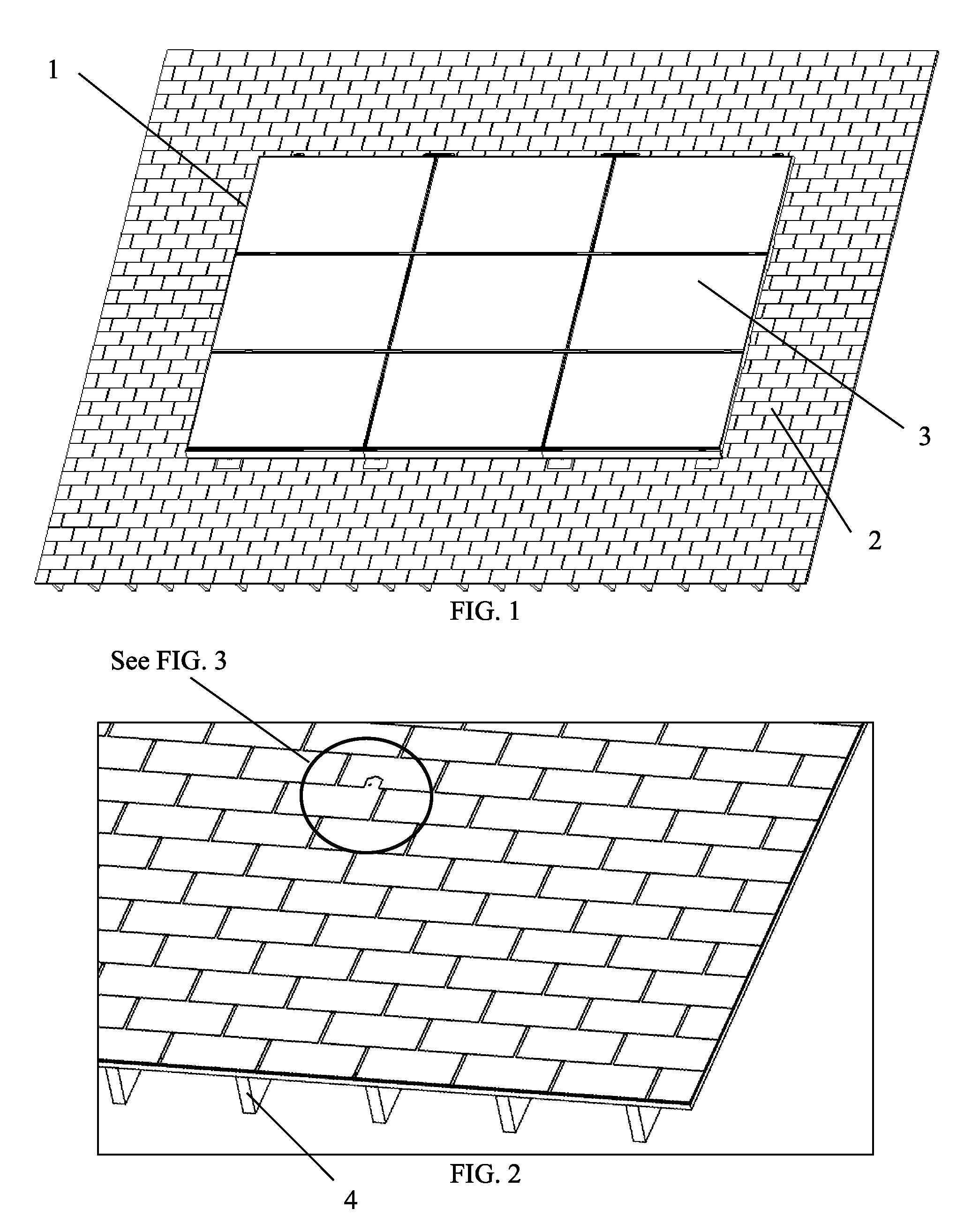
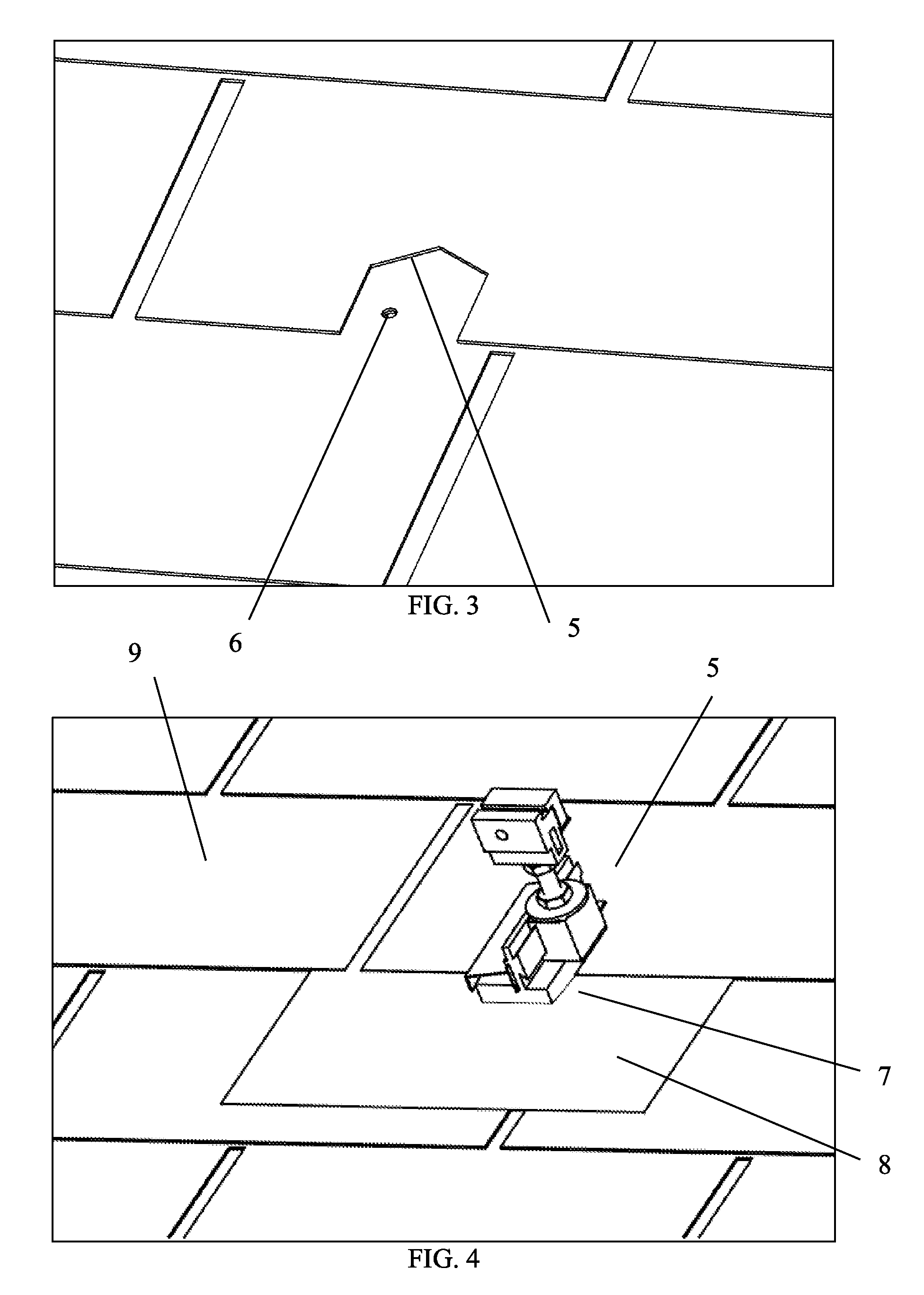
[0192]FIG. 1 shows a solar panel support system, 1, on a pitched roof, 2. Shown are 6 solar panels, 3, in an embodiment of a solar panel mounting or support system, 1. FIG. 2 shows the lower right corner of FIG. 1 without the solar panel support system, 1. In order to attach the roof mount, 7, a hole may be drilled into the roof, 2, into the roof rafter, 4, as shown in FIGS. 2, 3, and 4. The drilled hole, 6, can be seen in FIG. 3. The roof mount, 7, shown in FIG. 4 is one aspect of the invention. FIG. 5, shows numerous the roof mounts, 7, installed on the roof, 2.

[0193]FIGS. 6 and 8 show one embodiment of a solar panel mount base, 13, also referred to a mount channel, 13, as such may include a slide adjustment. As the cross section view in FIG. 9 shows, the flashing, 8, may be pinched into the solar panel mount base, 13, on the roof mount, 7, such as at location 18 and may be inserted under the cut shingle, 5 and the shingle, 9, and aligned to the drilled hole, 6. See FIGS. 3 and 4....


PUM

PropertyMeasurementUnit
movement restraintaaaaaaaaaa
movementaaaaaaaaaa
dissociationaaaaaaaaaa

Abstract

Solar panel array with a plurality of solar panels on support system attached at corners or off such corners for foundation structure needs and irregularities secured to roof by lag bolt with mount channel and flashing pre-assembled into mount by crimp for positive seal and mount riser height adjustable can include bilateral or quadrilateral mounts, a coupler seat to affix panel to mount and lateral movement seat for solar panel. An intercalative junction piece, nut, or washer has tines for grounding, a dissociation guide and flexture and keeps off the surface for association and perforation to clamp panel firmly via different clamps including wedge clamps, top restraints, lip end clamps, side support clamps, compression clamps, etc.

Description

CROSS-REFERENCES TO RELATED APPLICATIONS[0001]This application is a continuation of International Patent Application Number PCT / US14 / 33697, filed Apr. 10, 2014, which claims the benefit of and priority to, and this application also separately claims the benefit of and priority to U.S. Provisional Application No. 61 / 966,652, filed Feb. 26, 2014, U.S. Provisional Application No. 61 / 965,167, filed Jan. 24, 2014, and U.S. Provisional Application No. 61 / 958,564, filed Jul. 31, 2013, each hereby incorporated by reference herein in their entirety.BACKGROUND OF THE INVENTION[0002]This patent relates to solar panel mounting and support systems such as may be used for pitched roofs and other applications. It especially relates to mounting systems that are very easy and quick to install and that have low overall cost.[0003]Solar panel mounting systems have provided a number of features, however none has adequately provided specific features and adequately combined features that make an economi...

Claims


Application Information

Patent Timeline
Patent Type & Authority Patents(United States)
IPC IPC(8): E04D13/18F24J2/52F24J2/46
CPCF24J2/5245F24J2/465Y02B10/12F24S25/35F24S25/61F24S25/632F24S25/634F24S25/636F24S25/70F24S2025/021Y02B10/10Y02B10/20Y02E10/47Y02E10/50Y10T29/49947Y10T403/32532F16M13/022F24S80/70H02S20/10H02S20/23H02S20/30
Inventor PATTON, JOHN C.LINDSTROM, TODDHAFTER, ERIC
Owner IRONRIDGE
Why Eureka
Try Eureka