
Carbon reamer handle

a technology of reamer handle and reamer, which is applied in the field of carbon reamer handle, can solve the problems of limiting mobility and the ability to perform daily living activities, requiring a longer recovery period and rehabilitation time for patients, and prior art reamer spindles are not ideal for mis approaches, so as to achieve the effect of convenient removal

Active Publication Date: 2015-07-14
VIANT AS&O HLDG LLC
View PDF19 Cites 24 Cited by
  • Summary
  • Abstract
  • Description
  • Claims
  • Application Information

AI Technical Summary

Benefits of technology

The patent describes a reamer spindle that has a removable handle made of lightweight but durable material such as carbon fiber. The handle can be easily removed and positioned in different ways around the spindle. Additionally, the elongate housing of the reamer spindle is designed with a rounded low profile surface that helps to prevent damage to muscle tissue during use.

Problems solved by technology

The usual reasons for hip replacement are osteoarthritis, rheumatoid arthritis and traumatic arthritis, all of which can cause pain and stiffness that limit mobility and the ability to perform daily living activities.
However, such procedures require a longer recovery period and rehabilitation time for the patient.
These prior art reamer spindles are not ideal for MIS approaches.
The straight design and fixed handle orientation impedes the tool's ability to be used in small, tortuous spaces within the body, particularly of MIS procedures.

Method used


Image

  • Carbon reamer handle
  • Carbon reamer handle
  • Carbon reamer handle

Examples


Embodiment Construction

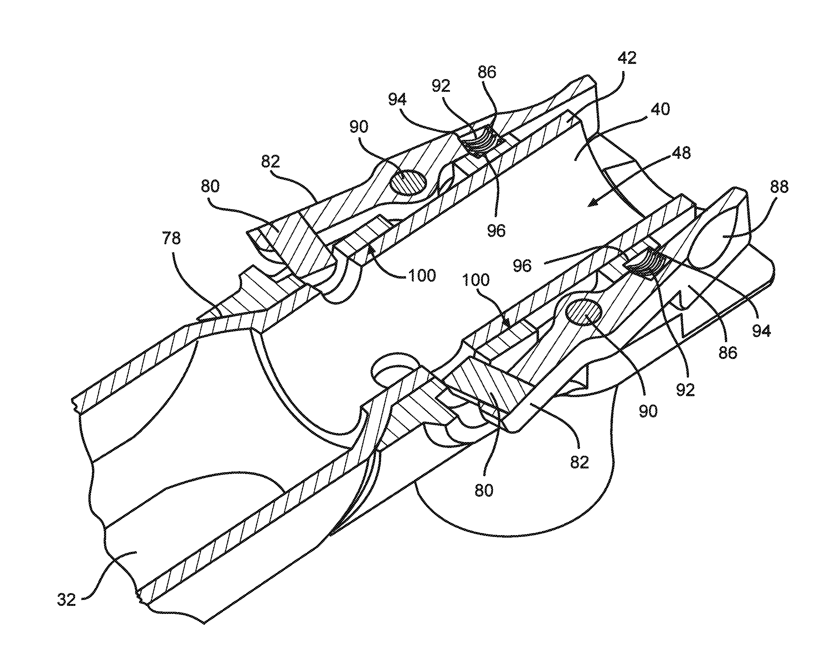
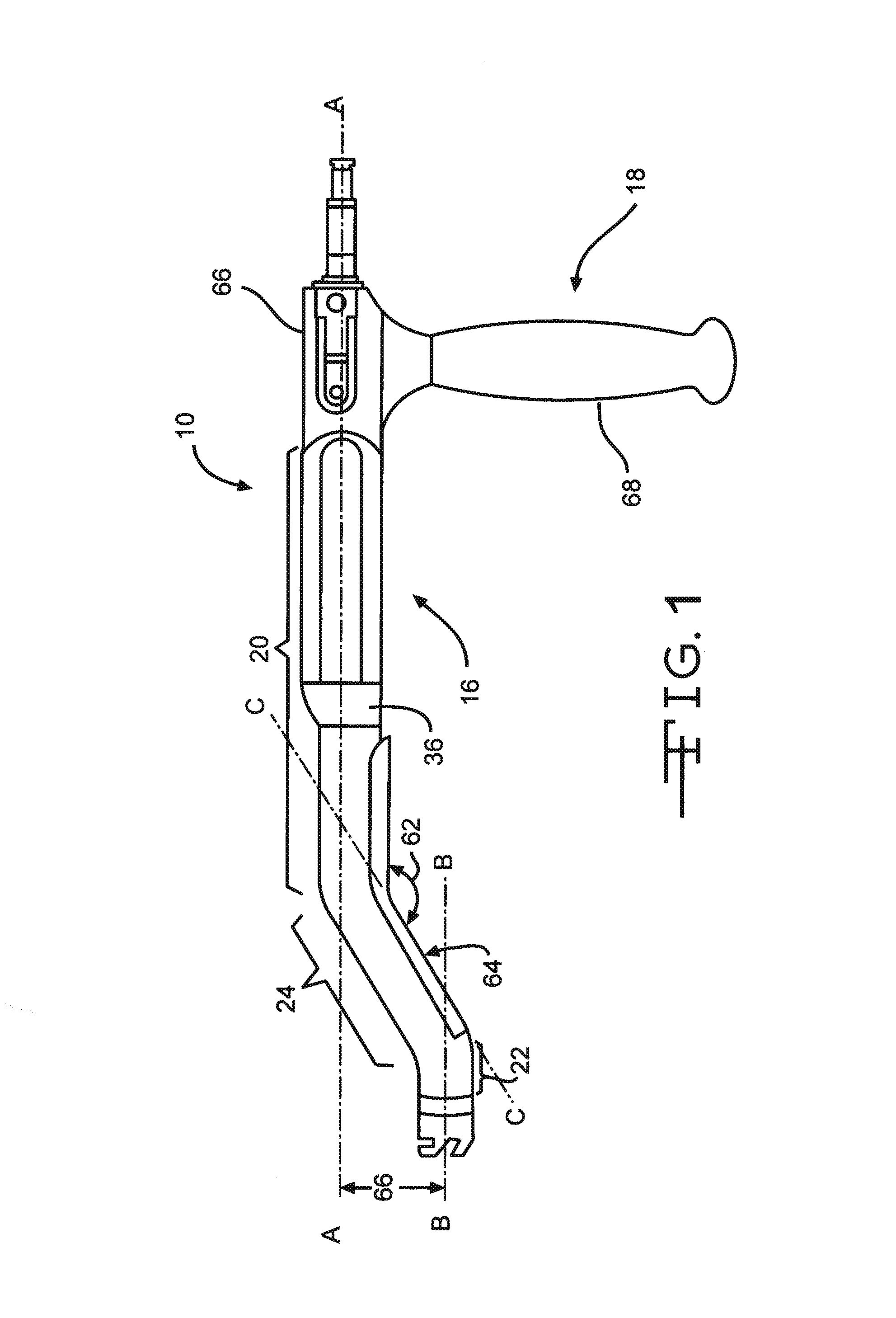
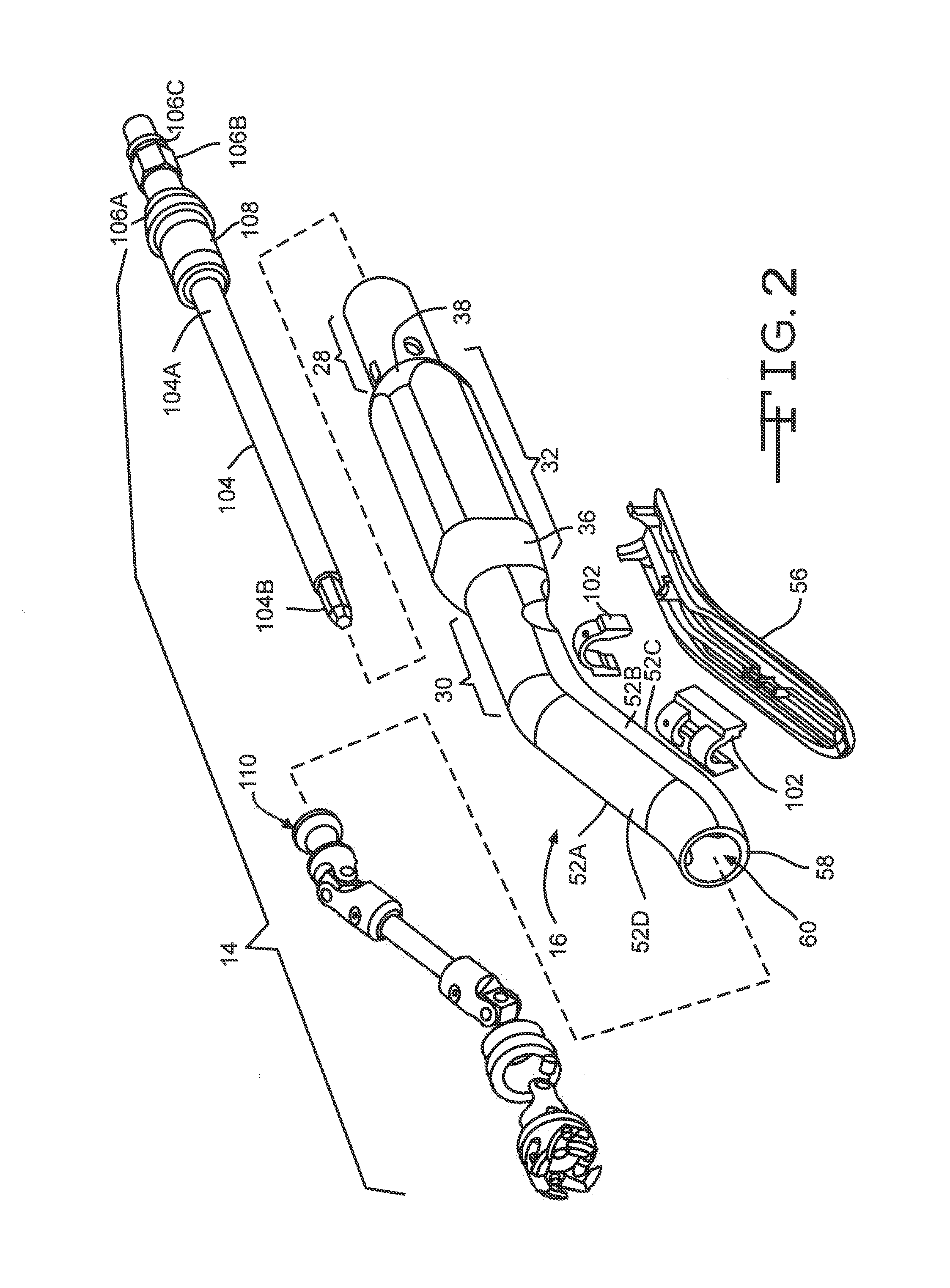
[0028]Turning now to the drawings, FIGS. 1 and 2 illustrate a reamer spindle 10 according to the present invention. The reamer spindle 10 is connectable to a reamer 12 (FIG. 12) for performing a minimally invasive hip replacement surgery. The reamer spindle 10 generally comprises a drive train 14 disposed within a housing 16. A handle assembly 18 is adjustably connected to the housing 16 spaced from the reamer 12.

[0029]The housing 16 has a length that extends from a proximal end portion to a distal end portion. Specifically, the housing 16 extends from a main housing section 20, located at the proximal end portion, to a distal neck section 22 with an intermediate housing section 24 therebetween. An opening 26 resides within the housing that extends from the main housing section 20 through the distal neck section 22.

[0030]The main housing section 20 further comprises a proximal main housing portion 28, a distal main housing portion 30 and a central main housing portion 32 therebetwee...


PUM


Abstract

A reamer for use in minimally invasive hip replacement surgical approaches is provided. The reamer spindle includes an offset elongate housing portion that extends from a proximal housing end portion a distal housing end portion. A handle assembly, preferably comprising a durable lightweight material such as carbon fiber that is removably connectable to the housing of the reamer spindle. A reamer head is removably connectable to the distal neck portion and has a surface configured to cut bone.

Description

CROSS REFERENCE TO RELATED APPLICATIONS[0001]This application claims priority to U.S. provisional application Ser. Nos. 61 / 410,418, filed on Nov. 5, 2010.BACKGROUND OF THE INVENTION[0002]Nearly 200,000 hip replacements are performed each year in the United States and the number is expected to continue to grow as the population ages. The usual reasons for hip replacement are osteoarthritis, rheumatoid arthritis and traumatic arthritis, all of which can cause pain and stiffness that limit mobility and the ability to perform daily living activities. Hip replacement surgery is usually performed when other measures (e.g., physical therapy, medications, and walking aids) are unable to overcome the chronic pain and disability associated with these conditions.[0003]Various techniques are used by orthopedic surgeons to perform hip replacements. These include the following approaches: anterior, antero-lateral, anterior, posterior, and postero-lateral. The posterior and posteolateral approache...

Claims


Application Information

Patent Timeline
IPC IPC(8): A61B17/16
CPCA61B17/1631A61B17/1664A61B17/1666A61B2017/0042A61B17/1671A61B2017/00831A61B2017/0046
Inventor ROSSE, YANN
Owner VIANT AS&O HLDG LLC
Learn More