
Automotive auxiliary ladar sensor

a technology of ladar sensor and auxiliary ladar, which is applied in the direction of instruments, transportation and packaging, and using reradiation, etc., can solve the problems of driving and passengers of automobiles being exposed to dangers

Active Publication Date: 2015-06-30
CONTINENTAL AUTONOMOUS MOBILITY US LLC
View PDF8 Cites 64 Cited by
  • Summary
  • Abstract
  • Description
  • Claims
  • Application Information

AI Technical Summary

Problems solved by technology

The driver and passengers of an automobile are exposed to dangers from other vehicles and a number of road hazards.
Stereo systems, holographic capture systems, and those which acquire shape from motion, have all been proposed and in some cases demonstrated, but what is lacking is a system with the capability of rapidly capturing 3-D images of objects and roadway features in the path of a moving vehicle, or travelling on an intersecting path, and which controls and adapts the host vehicle so as to avoid collisions and road hazards, and steer the best path.

Method used


Image

  • Automotive auxiliary ladar sensor
  • Automotive auxiliary ladar sensor
  • Automotive auxiliary ladar sensor

Examples


Embodiment Construction

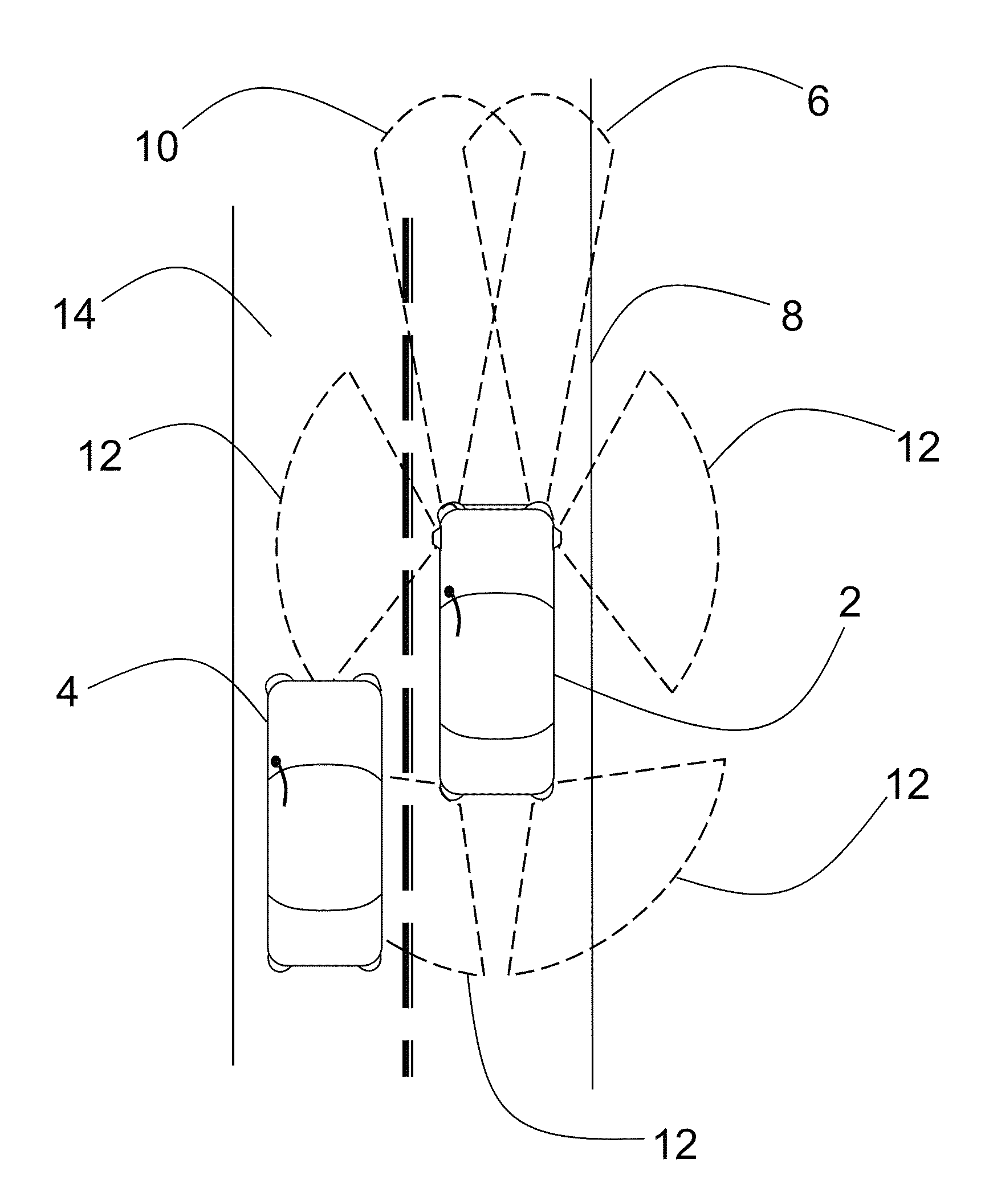
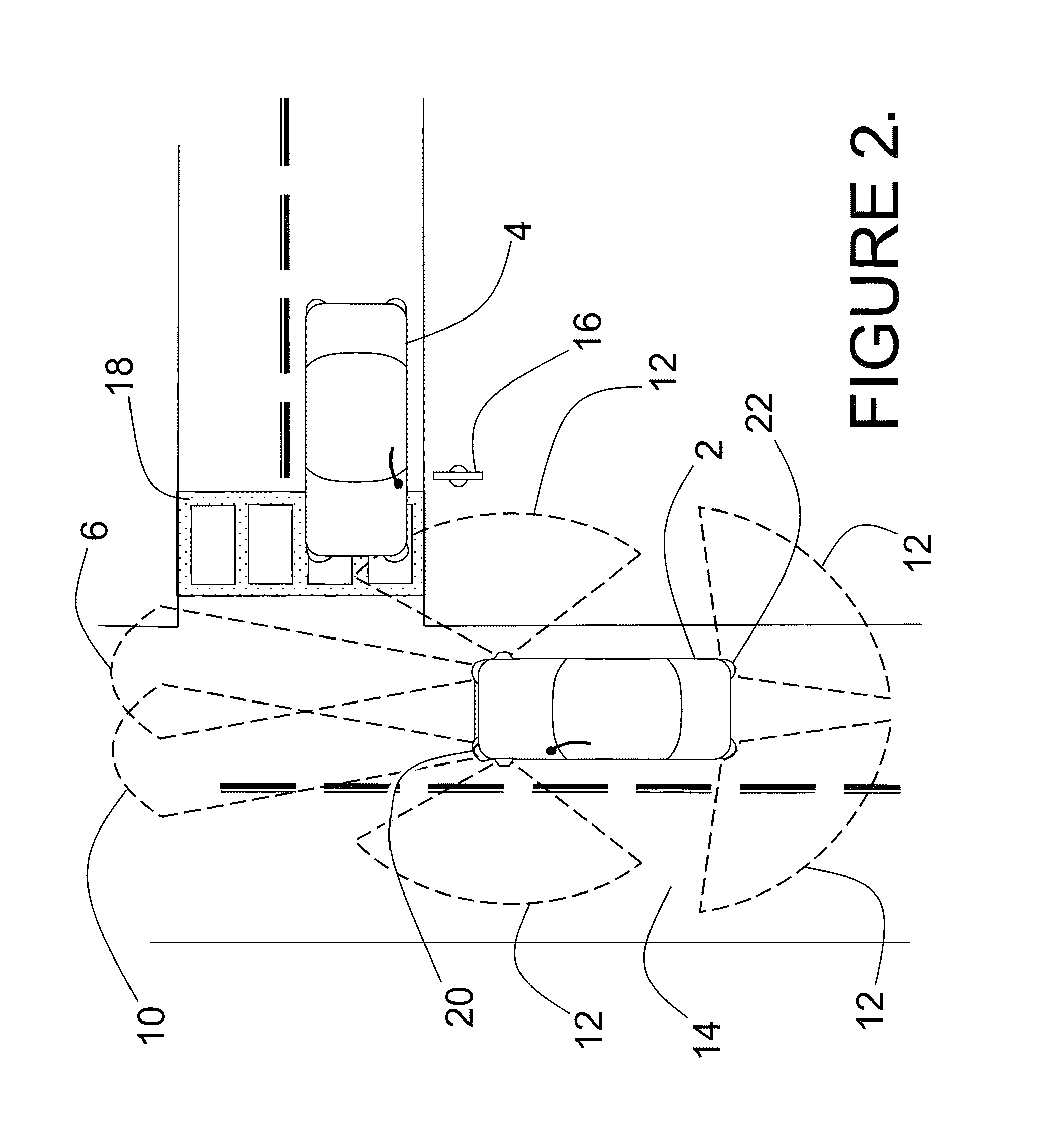
[0029]This application contains new subject matter related to previous U.S. Pat. Nos. 5,696,577, 6,133,989, 5,629,524, 6,414,746, 6,362,482, D463,383, and U.S. patent application Ser. No. 10 / 066,340 filed on Jan. 31, 2002 and published as US 2002 / 0117340 A1, the disclosures of which are incorporated herein by reference.

[0030]The embodiments disclosed herein enable a system for collision avoidance, object and obstacle recognition and avoidance, and ride and steering control improvements. The benefits are realized through the use of a 3-D imaging facility, comprising a vehicle mounted ladar system with an object detection and recognition capability, a steering, braking, and accelerator control system, and a ride and suspension modification system. The vehicle mounted ladar system may comprise a number of side mounted, rear mounted, or forward looking ladar sensors connected to a central ladar system controller which synthesizes the available data from each of the independent ladar sen...


PUM


Abstract

A vehicle and ladar sensor assembly system is proposed which makes use of forward mounted long range ladar sensors and short range ladar sensors mounted in auxiliary lamps to identify obstacles and to identify potential collisions with the vehicle. A low cost assembly is developed which can be easily mounted within a body panel cutout of a vehicle, and which connects to the vehicle electrical and computer systems through the vehicle wiring harness. The vehicle has a digital processor which interprets 3D data received from the ladar sensor assembly, and which is in control of the vehicle subsystems for steering, braking, acceleration, and suspension. The digital processor onboard the vehicle makes use of the 3D data and the vehicle control subsystems to avoid collisions and steer a best path.

Description

BACKGROUND[0001]1. Field[0002]The embodiments disclosed herein relate generally to 3-D image generation and the identification of objects, tracking of objects, road hazard avoidance, and collision avoidance in short range automotive applications and more particularly to a ladar sensor assembly having a laser transmitter, laser sensor and digital processor integrated in an envelope inserted into a vehicle body panel.[0003]2. References to Related Art[0004]The 3-D imaging technology disclosed in Stettner et al, U.S. Pat. Nos. 5,446,529, 6,133,989 and 6,414,746 provides with a single pulse of light, typically pulsed laser light, all the information of a conventional 2-D picture along with the third dimensional coordinates; it furnishes the 3-D coordinates of everything in its field of view. This use is typically referred to as flash 3-D imaging in analogy with ordinary digital 2-D cameras using flash attachments for a self contained source of light. As with ordinary 2-D digital cameras...

Claims


Application Information

Patent Timeline
Patent Type & Authority Patents(United States)
IPC IPC(8): G06F17/10G01S7/481G01S17/89G01S17/02B60Q1/00G01S17/93G01S7/489G01S17/86G01S17/894G01S17/931
CPCG01S17/936B60Q1/0023G01S17/023G01S17/89G01S7/481G01S7/4813G01S7/4818G01S7/489G01S17/86G01S17/931G01S17/894B60T7/22B60W30/08B60W2420/52B62D15/0265
Inventor STETTNER, ROGERGILLILAND, PATRICKDUERNER, ANDREW
Owner CONTINENTAL AUTONOMOUS MOBILITY US LLC
Learn More