
Dismountable helicopter

a helicopter and tail section technology, applied in the direction of airflow influencers, fuselages, transportation and packaging, etc., can solve the problem that the helicopter type is not unmanned, and achieve the effect of easy mounting and dismounting of the tail section

Active Publication Date: 2015-06-30
UMS SKELDAR SWEDEN AB
View PDF14 Cites 2 Cited by
  • Summary
  • Abstract
  • Description
  • Claims
  • Application Information

AI Technical Summary

Benefits of technology

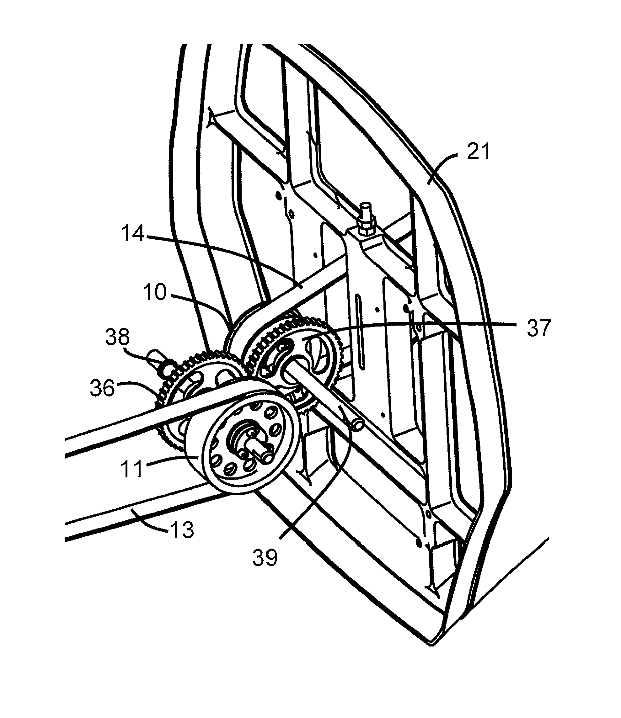
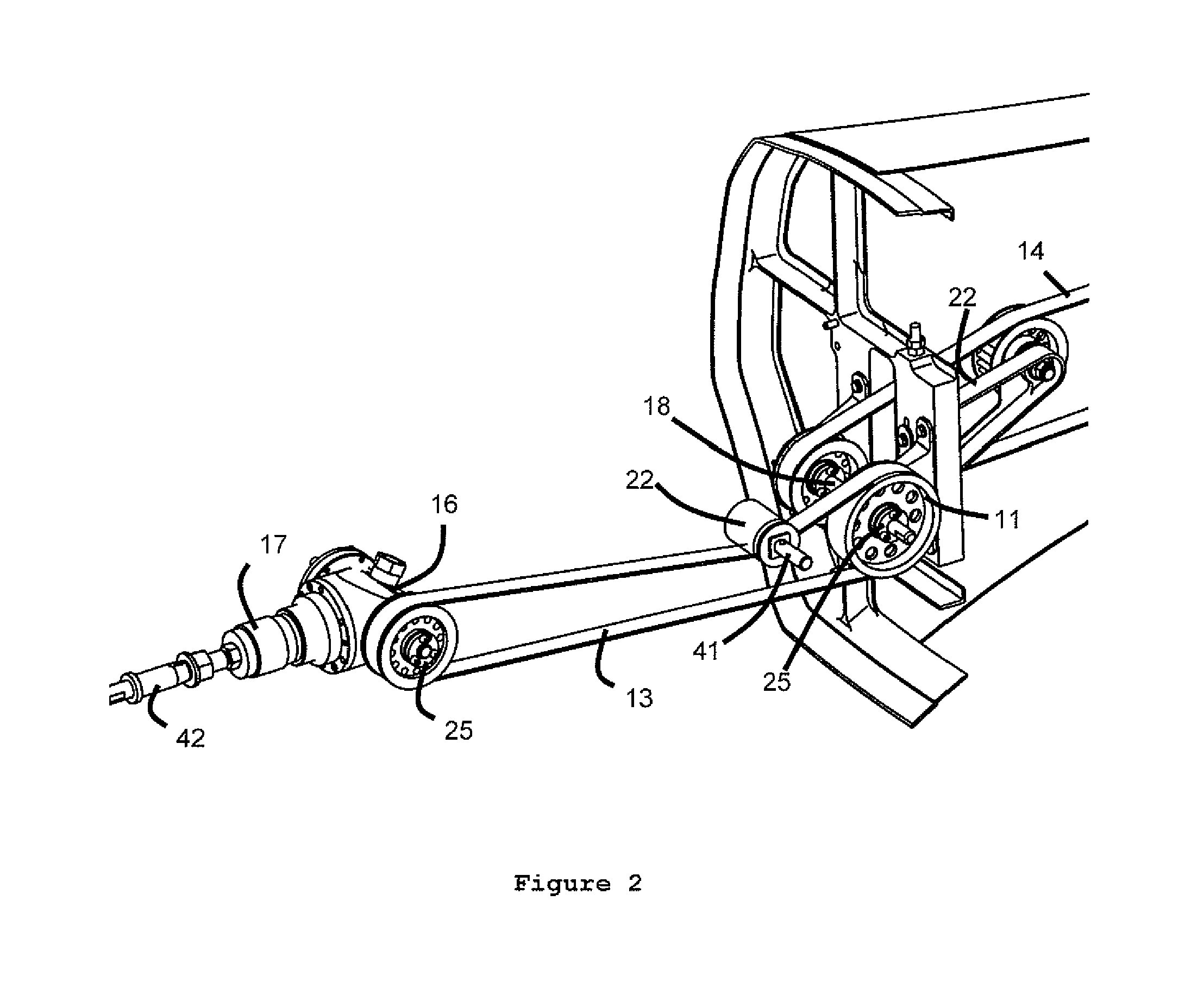
[0012]In one embodiment of the invention, the mechanical coupling means comprises a common drive shaft to which said second pulley of said first pulley-and-belt-drive arrangement and said first pulley of said second pulley-and-belt-drive arrangement are fixedly connected, preferably by a torque-proof connection. With “torque-proof” is meant that the two pulleys are fixed to the same common drive shaft, such that rotational movement of the two pulleys relative to each other is avoided.
[0013]The common drive shaft may comprise two parts, releasably connectable to each other to form a torque-proof connection. Any suitable type of shaft coupling means can be used. The releasable connection between the two parts of the common drive shaft is preferably between the two pulleys fixedly connected to the common drive shaft. Suitable connections between the first and second part of the common drive shaft are known in the art. Preferred connections are form-locking connections, such as form-locking plug connections, e.g., a torx connection. In one embodiment, an external jacket having protrusions and / or indentations cooperating with corresponding indentations and / or protrusions on the common drive shaft can be used to accomplish the torque-proof connection. Provision of a common drive shaft having two connectable parts, as described above, allows easy mounting and dismounting of the tail section of the helicopter, without the need to connect or disconnect belts to and from the first and / or second pulley and belt drive arrangement.
[0014]In an alternative embodiment said coupling means comprises a gearwheel connection (or a gearwheel coupling) between said second pulley of said first pulley-and-belt-drive arrangement and said first pulley of said second pulley-and-belt-drive arrangement. The gear-wheel connection allows assembling the tail section to the front section without having to pull a respective belt over the respective pulleys.
[0016]Preferably, the belt is a toothed belt. Toothed belts provide for low maintenance, for example, no lubrication is required. If appropriately installed, toothed belts effectively avoid slippage.

Problems solved by technology

This type of helicopter is, however, not unmanned and its tail rotor is driven by a drive shaft.

Method used


Image

  • Dismountable helicopter
  • Dismountable helicopter
  • Dismountable helicopter

Examples


Embodiment Construction

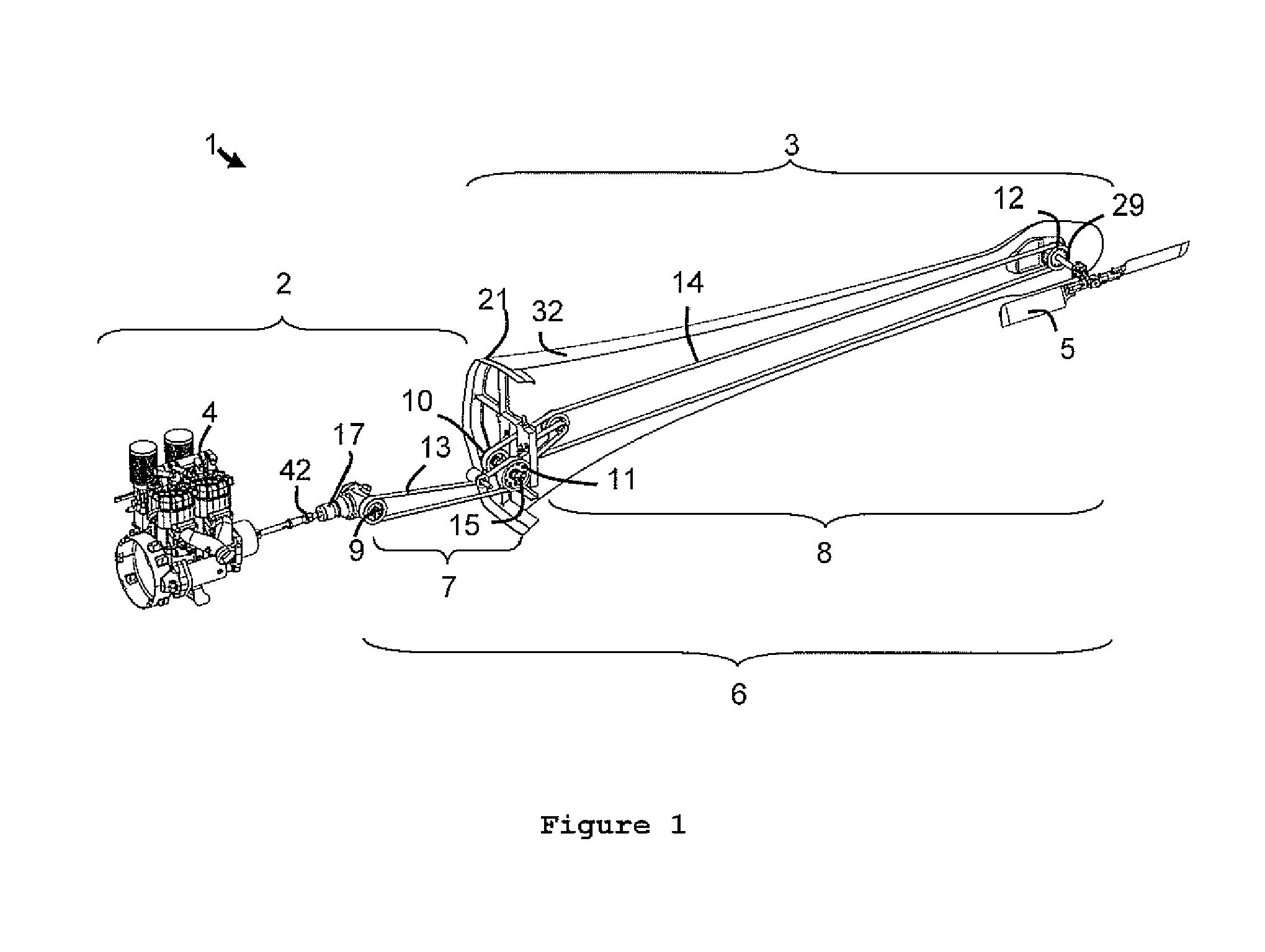
[0029]The present invention relates to a dismountable helicopter 1 that allows for dismounting of its tail section 3 from its front section 2. Helicopter 1 is preferably an unmanned aerial vehicle (UAV) helicopter.

[0030]As can best be seen in FIG. 1, power transmitting means 6 is provided for power transmission between a motor 4 and tail rotor 5. Power transmitting means 6 comprises two parts: a first pulley-and-belt-drive arrangement 7, and a second pulley-and-belt-drive arrangement 8, the two parts being mechanically coupled for power transmission by coupling means 15. The pulley-and-belt-drive arrangements 7 and 8 are coupled via coupling means 15 at the intersection of front section 2 and the tail section 3. The pulley-and-belt-drive arrangements 7 and 8 are light-weight when compared to drive shaft constructions. The pulley-and-belt-drive concept supports low noise operation of the helicopter. The separation of the dismountable tail section 3 from the front section 2 makes the ...


PUM


Abstract

An unmanned aerial vehicle helicopter including a dismountable tail section including a torque compensating rotor. Power transmission from the motor to the torque compensating rotor is accomplished by pulley-and-belt drive arrangements.

Description

CROSS-REFERENCE TO RELATED APPLICATIONS[0001]This is the national phase under 35 U.S.C. §371 of PCT / SE2009 / 051365 filed 2 Dec. 2009.FIELD OF THE INVENTION[0002]The invention relates to an unmanned aerial vehicle (UAV) helicopter comprising a dismountable tail section with a torque compensating rotor, wherein power transmission from the motor to the torque compensating rotor is accomplished by pulley-and-belt drive arrangements.BACKGROUND OF THE INVENTION[0003]Unmanned helicopters are frequently used for exploration purposes. Such helicopters are often operated from ships. Therefore, UAV helicopters must be easily transportable and light-weight. Furthermore, UAV helicopters should be easy to store on a ship, when not in use. The propulsion of the rotors should thus allow for quick and easy assembly / disassembly of the helicopter, thereby simplifying transportation and storage. Additionally, UAV helicopters should be easy to maintain.[0004]Dismountable helicopters are generally known. ...

Claims


Application Information

Patent Timeline
Patent Type & Authority Patents(United States)
IPC IPC(8): B64C1/26B64C27/12B64C39/02B64C1/06B64C1/30B64C27/82
CPCB64C39/024B64C1/26B64C1/063B64C1/30B64C27/12B64C27/82B64C2201/024B64C2201/108B64U30/20B64U20/20B64U20/65B64U50/23B64U10/17B64U20/70B64U10/10
Inventor CARDELL, PER-ERIKSTENBOM, KJELLLIDSTROM, ROBERT
Owner UMS SKELDAR SWEDEN AB
Learn More