
Retaining clip for electrical connectors

a technology for electrical connectors and retaining clips, which is applied in the direction of magnets, coupling device connections, magnetic bodies, etc., can solve the problems of unreliable transmission operation, component failure or wear, and many long-lasting components of automatic transmissions, and achieve the effect of effective “fixing” and ease of disengagement of plugs

Inactive Publication Date: 2015-06-02
SONNAX TRANSMISSION CO
View PDF62 Cites 2 Cited by
  • Summary
  • Abstract
  • Description
  • Claims
  • Application Information

AI Technical Summary

Benefits of technology

This patent describes a method for securely attaching electrical connectors that allows for easy servicing. Specifically, there are several embodiments of a reusable retaining clip that can securely attach connectors, make them disengage with ease, or fix broken connectors. This enables the reuse of connectors and reduces waste. Overall, this method improves the reliability and efficiency of electrical connections.

Problems solved by technology

Automatic transmissions are expensive assemblies that include many long-lasting components.
However, there are internal components subjected to levels of vibration, temperature, and other stresses that result in component failure or wear while many of the drivetrain components are in usable condition.
However, these solenoids can encounter wear or breakage of the electrical connectors that result in unreliable operation of the transmission, or complete failure to operate.
Typically, these connectors are replaced, with the subsequent expenses of procuring new connectors and rebuilding portions of the solenoid assembly to incorporate the new connectors.
However, the back edge of the protrusion mates flatly against the bridge 3 and therefore the plug cannot be easily removed.
However, this often is ineffective because the amount of deflection required often breaks the bridge or permanently deforms the bridge.
This renders the locking mechanism useless if the linear pressure solenoid is reused.

Method used


Image

  • Retaining clip for electrical connectors
  • Retaining clip for electrical connectors
  • Retaining clip for electrical connectors

Examples


Embodiment Construction

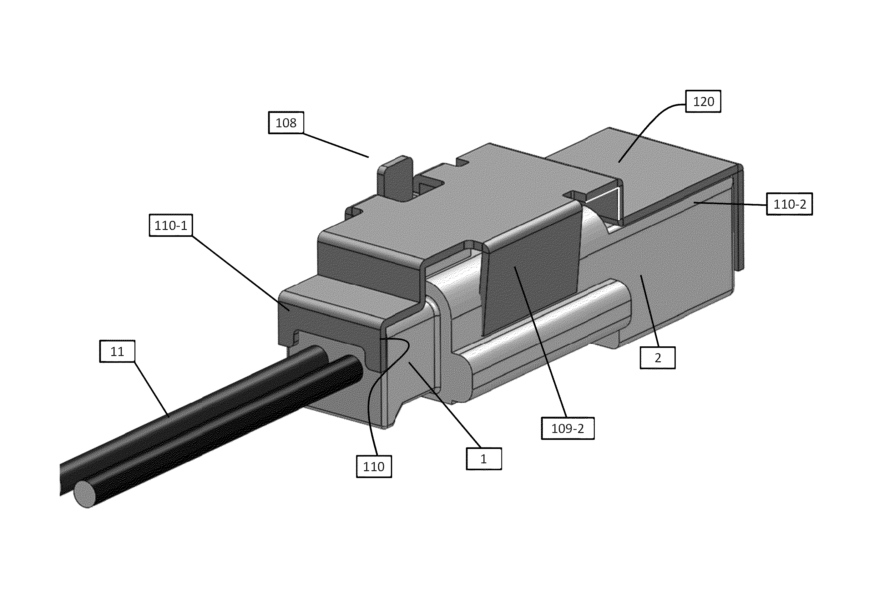
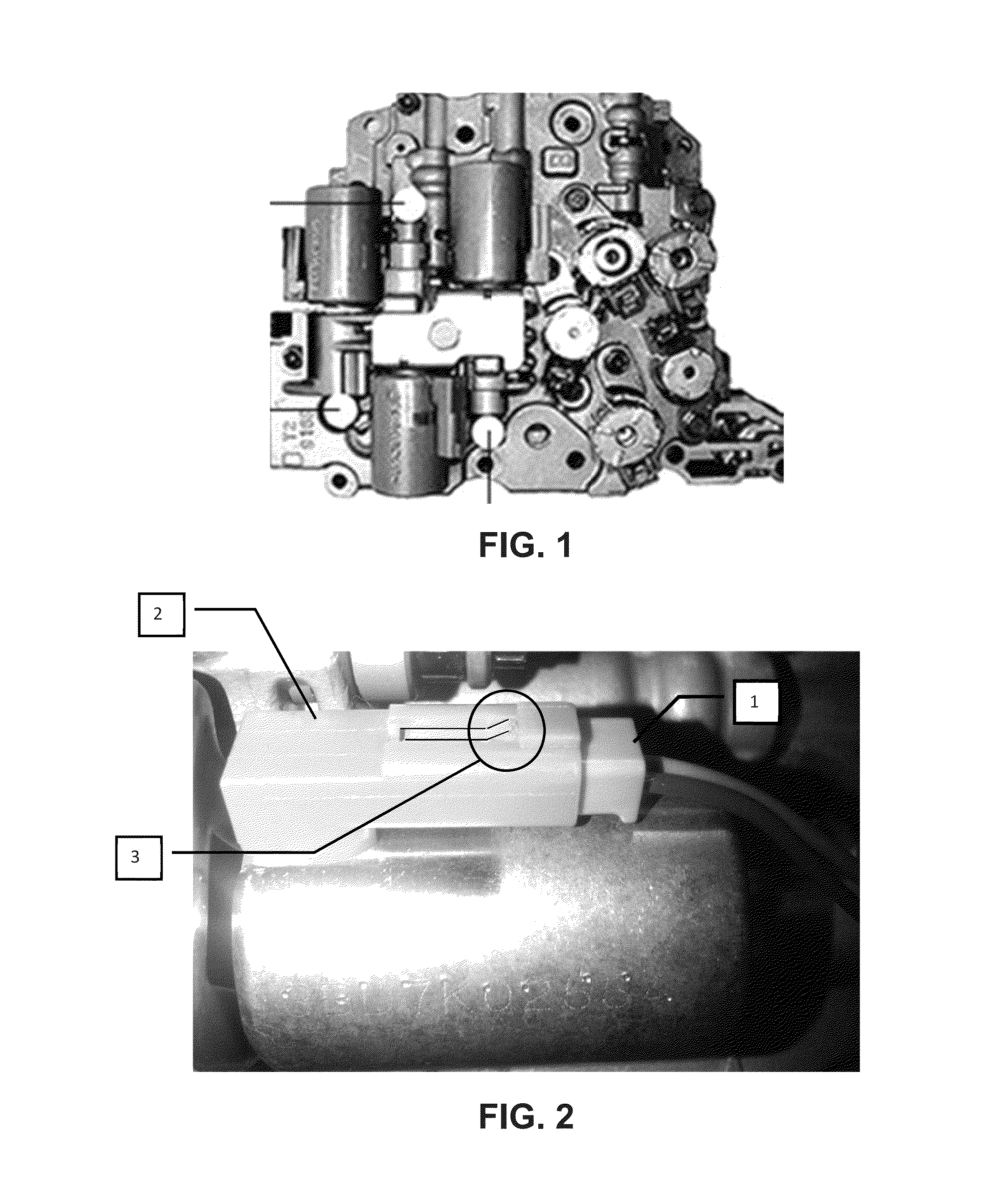
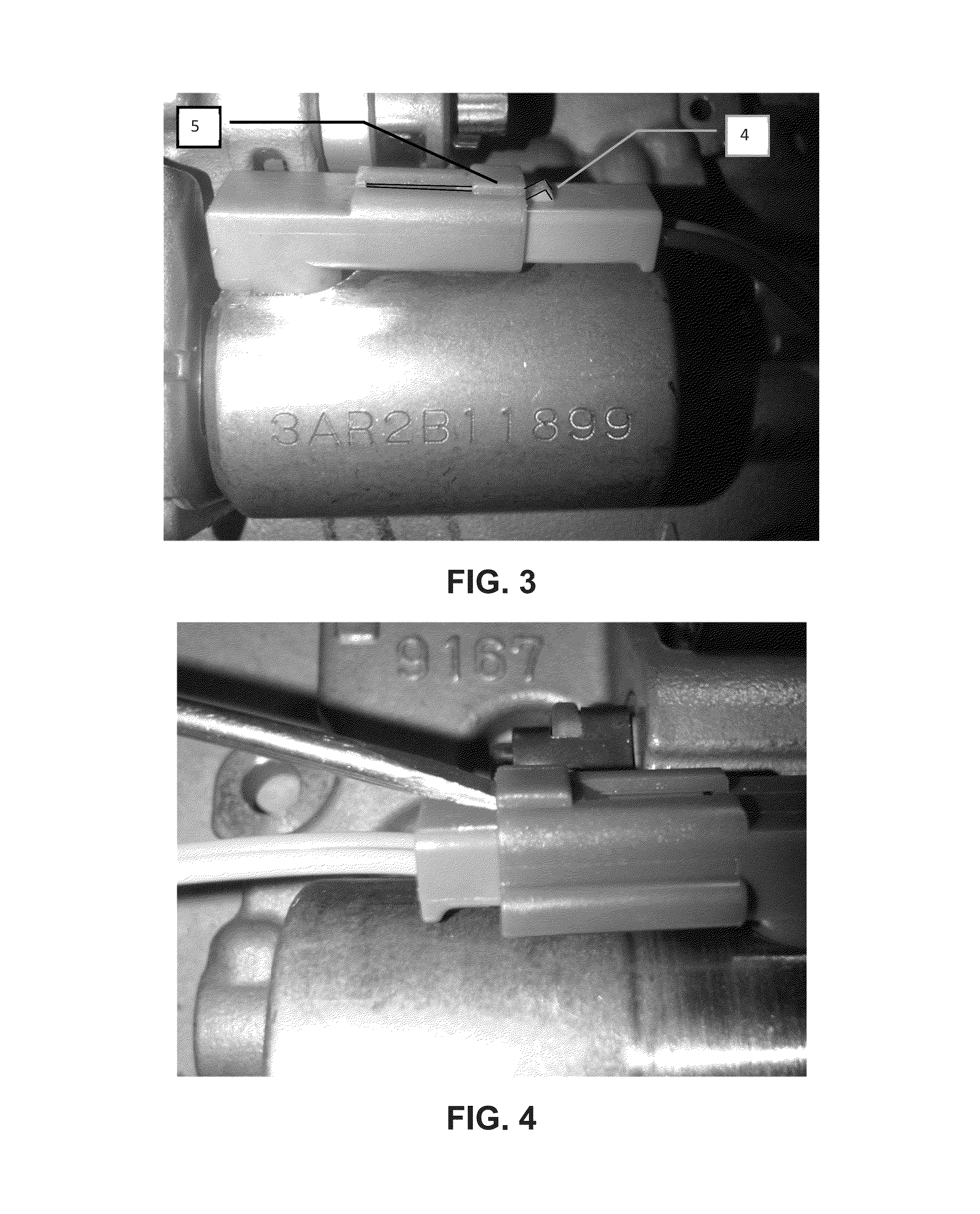
[0030]For the purposes of promoting an understanding of the principles of the invention, reference will now be made to the embodiments illustrated in the drawings and specific language will be used to describe the same. It will nevertheless be understood that no limitation of the scope of the invention is thereby intended, such alterations and further modifications in the illustrated device, and such further applications of the principles of the invention as illustrated therein being contemplated as would normally occur to one skilled in the art to which the invention relates. At least one embodiment of the present invention will be described and shown, and this application may show and / or describe other embodiments of the present invention. It is understood that any reference to “the invention” is a reference to an embodiment of a family of inventions, with no single embodiment including an apparatus, process, or composition that should be included in all embodiments, unless otherw...


PUM

PropertyMeasurementUnit
thicknessaaaaaaaaaa
distanceaaaaaaaaaa
shapeaaaaaaaaaa

Abstract

A retaining clip that provides a method for securing electrical connections between a male and female electrical connectors is disclosed. Current locking mechanisms are on both the electrical plug and the connector. These locking mechanisms often break when disconnecting the plug. Some embodiments of the present invention eliminate the need for the locking mechanisms. Furthermore, in cases where the mechanisms have been broken, some embodiments provide a method for reusing the electrical plug and / or the connector.

Description

CROSS REFERENCE TO RELATED APPLICATION[0001]This application claims the benefit of priority to U.S. Provisional Patent Application Ser. No. 61 / 613,808, filed Mar. 21, 2012; U.S. Provisional Patent Application Ser. No. 61 / 751,147, filed Jan. 10, 2013; and U.S. Provisional Patent Application Ser. No. 61 / 789,381, filed Mar. 15, 2013, incorporated herein by reference.FIELD OF THE INVENTION[0002]The present invention relates to apparatus and methods for retaining together assembled electrical connectors, and in some applications to electrical connectors within an automatic transmission.BACKGROUND OF INVENTION[0003]Automatic transmissions are expensive assemblies that include many long-lasting components. However, there are internal components subjected to levels of vibration, temperature, and other stresses that result in component failure or wear while many of the drivetrain components are in usable condition. In particular, automatic transmissions include one or more solenoid assemblie...

Claims


Application Information

Patent Timeline
Patent Type & Authority Patents(United States)
IPC IPC(8): H01R13/60H01R13/639H01R13/73H01R43/00H01R43/027
CPCH01R13/73H01R43/027H01R13/6395H01R43/002Y10T29/4902Y10T29/49021H01R13/502
Inventor FATHAUER, PAUL
Owner SONNAX TRANSMISSION CO
Learn More