
Power unit for utility vehicle

a power unit and utility vehicle technology, applied in vehicle components, vehicle propulsion parts, construction vehicles, etc., can solve the problems of increasing the weight of the entire vehicle and the weight of the subframe, and achieve the effect of accurately absorbing vibrations and simple dampers

Active Publication Date: 2015-06-02
KAWASAKI MOTORS LTD
View PDF5 Cites 9 Cited by
  • Summary
  • Abstract
  • Description
  • Claims
  • Application Information

AI Technical Summary

Benefits of technology

This configuration reduces the overall weight of the vehicle, allows for accurate and efficient connection of the engine and transmission without a sub frame, and effectively absorbs vibrations, enhancing mounting accuracy and stability.

Problems solved by technology

However, in a structure in which an engine and a transmission are mounted to a sub frame, the arrangement space for a power unit becomes larger, and further, the weight of the sub frame is heavy, thereby increasing the weight of the entire vehicle.

Method used


Image

  • Power unit for utility vehicle
  • Power unit for utility vehicle
  • Power unit for utility vehicle

Examples


Embodiment Construction

Embodiments of the Invention

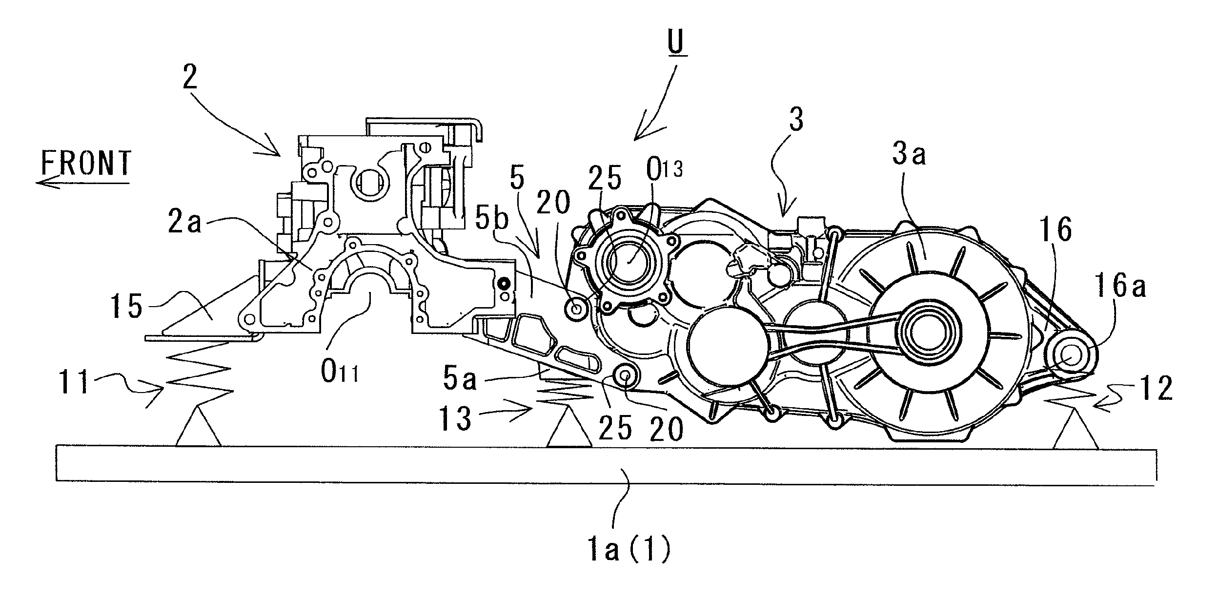
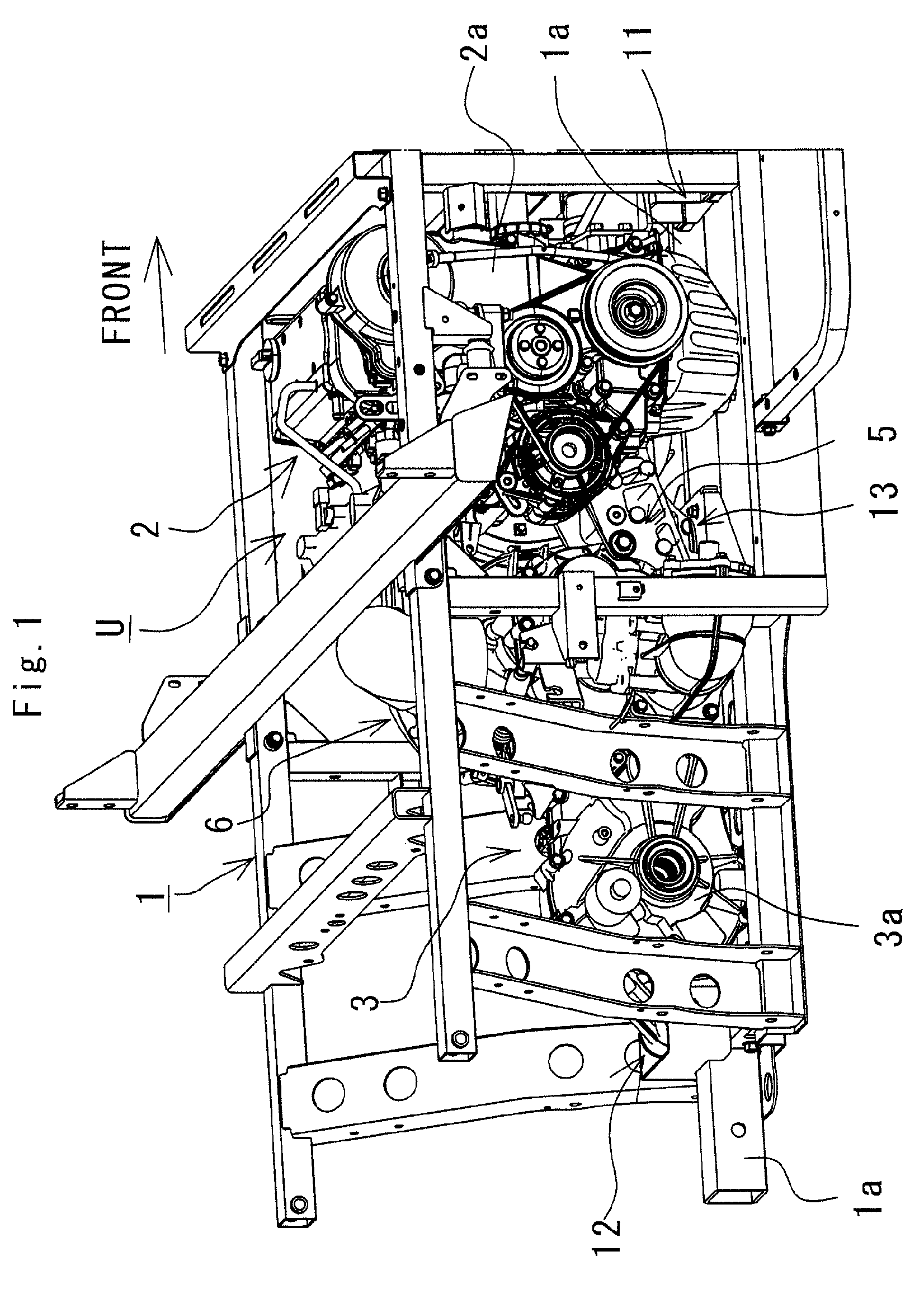
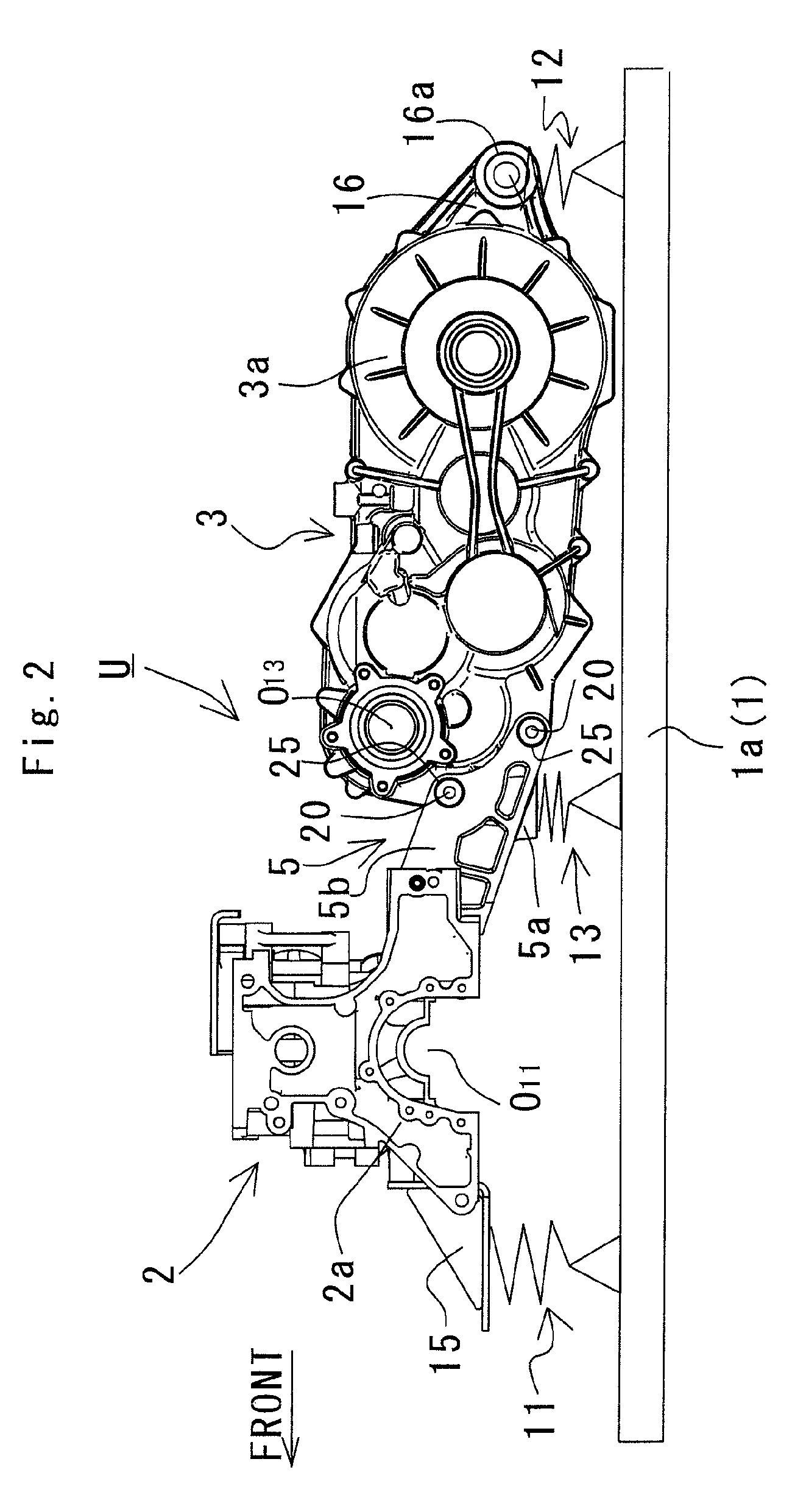
[0033]FIGS. 1 to 15 show a power unit for utility vehicle according to the present invention. A description will be given of one embodiment according to the present invention with reference to the attached drawings. For the sake of convenience of explanation, in the following descriptions, the lengthwise direction of an utility vehicle is referred tows the lengthwise direction of an engine and other component parts; and the right and left viewed from a passenger riding in the utility vehicle (the right and left viewed from behind the vehicle) in a vehicular widthwise direction are referred to as the right and left of the vehicle, the engine, and the other component parts.

[0034]FIG. 1 is a perspective view showing a power unit U, wherein a chassis frame 1 is constituted of a plurality of frame members and formed into a substantially rectangular shape being elongated in a vehicular lengthwise direction. The power unit U is disposed at a rear portion of the ...


PUM


Abstract

An engine and a transmission are connected to each other via a connecting bracket interposed therebetween in the vehicular lengthwise direction. The engine is provided with a first connector having a first mounting hole substantially parallel to a vehicle lengthwise direction, and a first tightening member to be inserted into the first mounting hole on a side opposite to the engine connects the first end of the connecting bracket to the first connector. The transmission is provided with a second connector having a second mounting hole penetrating in a vehicular widthwise direction, and a second tightening member to be inserted into the second mounting hole connects the second end of the connecting bracket to the second connector.

Description

BACKGROUND OF THE INVENTION[0001]1. Field of the Invention[0002]The present invention relates to a power unit for utility vehicle to be mounted to a chassis frame.[0003]2. Description of the Related Art[0004]A power unit for utility vehicle is configured by an engine, a transmission, and the like in a structure in which the transmission is formed independently of the engine, the transmission is molded integrally with a crank case for the engine, or the like. In the structure in which a transmission is formed independently of an engine, for example, the engine and the transmission are securely arranged on a sub frame in a lengthwise direction, and then, the sub frame is fixed to a chassis frame via a damper.[0005]However, in a structure in which an engine and a transmission are mounted to a sub frame, the arrangement space for a power unit becomes larger, and further, the weight of the sub frame is heavy, thereby increasing the weight of the entire vehicle. As a prior art document of...

Claims


Application Information

Patent Timeline
Patent Type & Authority Patents(United States)
IPC IPC(8): B60K5/12B60K5/04
CPCB60K5/1216B60K5/04B60Y2200/22B60Y2200/41
Inventor KOUMA, YUJIITOO, SEIJIMORITA, TAISUKEHAMADA, AYUMI
Owner KAWASAKI MOTORS LTD
Learn More