Eureka AIR delivers breakthrough ideas for toughest innovation challenges, trusted by R&D personnel around the world.

Real-time capable battery cell simulation

a battery cell and real-time capability technology, applied in secondary cell testing, complex mathematical operations, analog and hybrid computing, etc., can solve the problems of no longer being real-time capable, no longer being able to meet real-time requirements of models, and no longer being able to handle models, etc., to achieve optimization of storage and computation effort for calculating all relevant variables

Active Publication Date: 2015-04-28
DSPACE DIGITAL SIGNAL PROCESSING & CONTROL ENG
View PDF4 Cites 14 Cited by
  • Summary
  • Abstract
  • Description
  • Claims
  • Application Information

AI Technical Summary

Benefits of technology

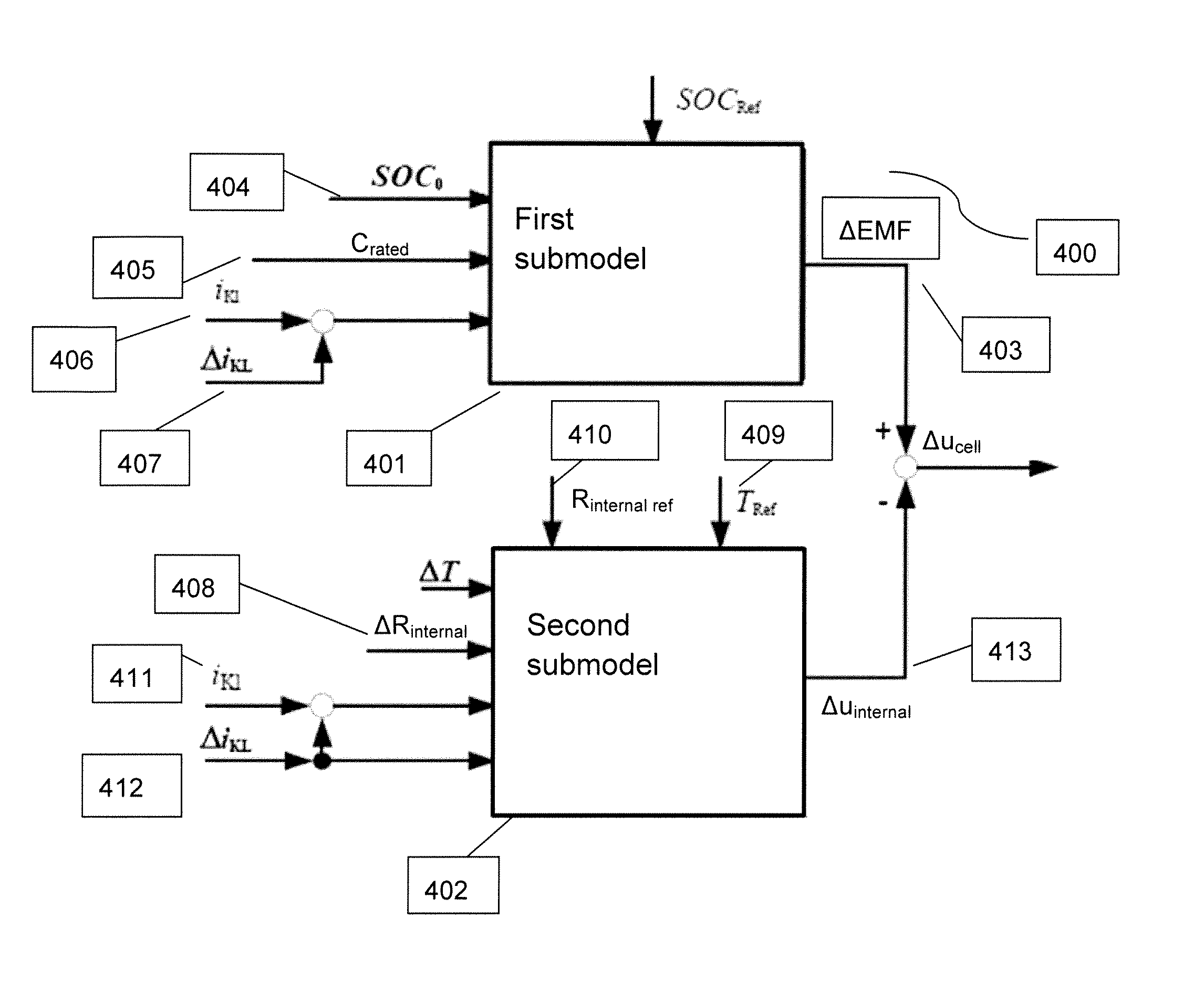
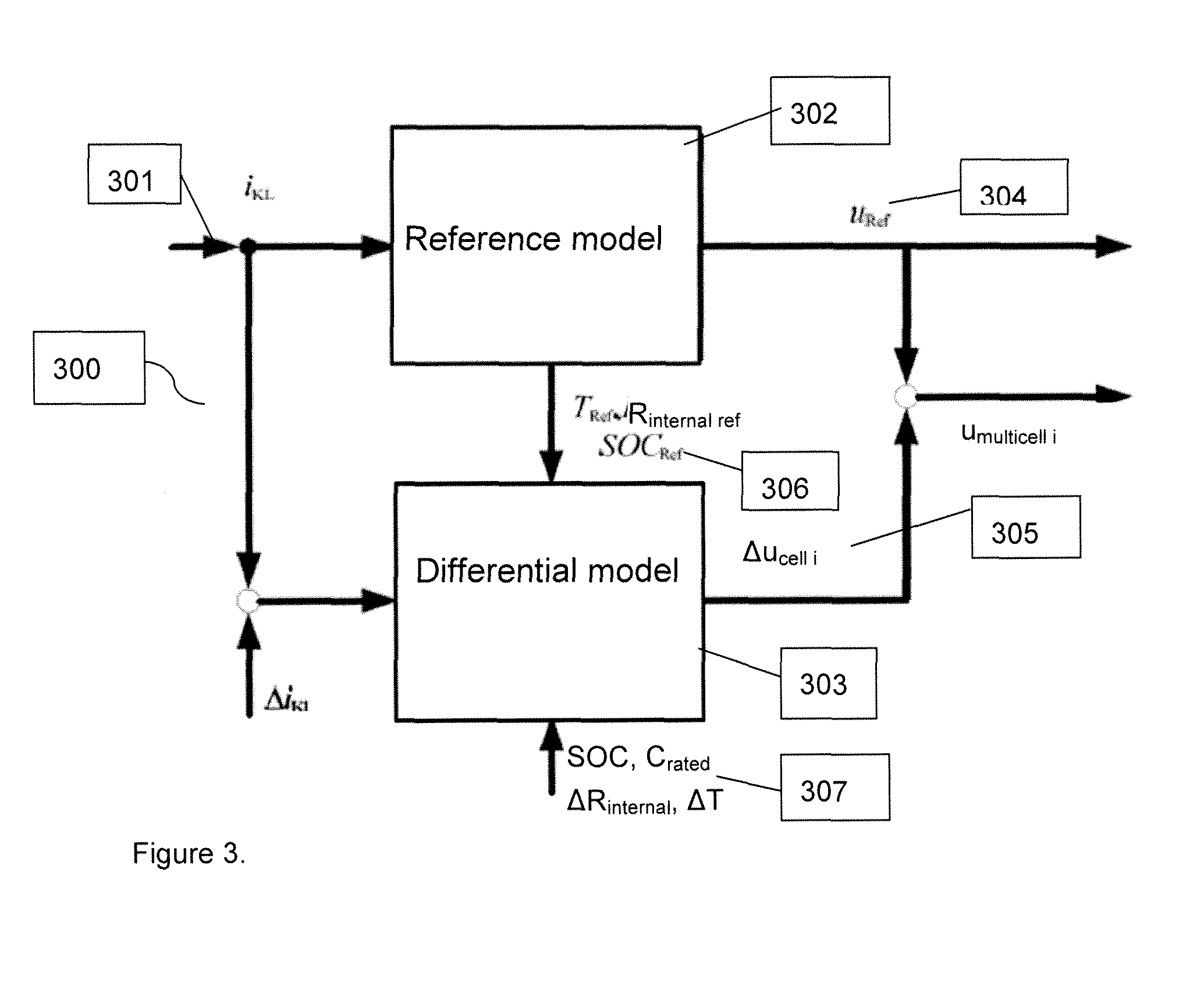
[0015]One advantage of the method and system according to the present invention is that the computation effort for calculating all the relevant variables of the reference cell and of the additional single cells is greatly reduced by means of the method according to the present invention in comparison with the calculation of said variables by means of n single cell models. Thus a real-time simulation for a battery with a much larger number of single cells is made possible. The use of storage is also optimized.

Problems solved by technology

However, such a model is no longer easy to handle when there are a large number of single cells; beyond a certain number of single cells, it is also no longer real-time capable.
This means that even when using specialized hardware for HIL simulations, the real-time requirements of the models can no longer be met.
Testing of a control unit, which also tests the response time of a control unit, for example, therefore cannot be performed under conditions which reflect reality.
The possibility of simulating only one single cell and scaling the output variables by multiplying them times the number of cells n is not feasible for testing of BMS because in this case parameter controls and different states of charge of the single cells can no longer be modeled.

Method used


Image

  • Real-time capable battery cell simulation
  • Real-time capable battery cell simulation
  • Real-time capable battery cell simulation

Examples


Embodiment Construction

[0034]A system and method for real-time simulation of a battery comprising simulating a cell array by means of an overall model on a computer unit is disclosed. The model of the cell array includes a plurality of single cells, a plurality of terminal voltages for the plurality of single cells, a plurality of terminal currents for the plurality of single cells, a total input current and cell parameters or variables for the plurality of single cells. The system and method disclosed further comprises connecting the computer unit via a cell voltage emulator to a control unit test system; calculating the plurality of terminal voltages of the plurality of single cells on the computer unit by using the overall model; and supplying the calculated plurality of terminal voltages of the plurality of single cells to the control unit test system by means of the cell voltage emulator. The overall model comprises a first model wherein a first single cell is modeled by means of the first model as a...


PUM

PropertyMeasurementUnit
terminal voltagesaaaaaaaaaa
voltageaaaaaaaaaa
currentaaaaaaaaaa

Abstract

A system for real-time simulation of a battery comprising simulating a cell array by an overall computer model is disclosed. The model includes a plurality of single cells. A computer is connected via a cell voltage emulator to a control unit calculating terminal voltages of single cells by using the overall model and supplying the calculated terminal cell voltages to the control unit by the cell voltage emulator. The overall model comprises a first model which models a first single reference cell having cell parameters typical of the cell array and sending the total input current of the cell array to the first model as an input variable. The terminal voltage of the reference cell is calculated by the first model. The overall model further comprises a second model which calculates a deviation in the terminal voltage of an additional single cell from the terminal voltage of the reference cell.

Description

CROSS REFERENCE TO RELATED APPLICATIONS[0001]The present invention claims rights of priority to German Patent Application No. 10 2010 062 838.7, filed on Dec. 10, 2010, which is hereby incorporated by reference.FIELD OF THE INVENTION[0002]The invention relates to a method for simulating battery cells for testing a control unit and a system for simulating a battery comprising a cell array made up of a plurality of single cells.BACKGROUND OF THE INVENTION[0003]Hardware-in-the-loop (HIL) is a technology that is widely used for early testing and verification of the functionality of control units, e.g., in the automotive field. In this method, actual control units are tested in interaction with components simulated in real time to determine the extent to which they comply with the specified requirements. The environment of the control unit to be tested, consisting of actuators, sensors and the processes in the vehicle, is simulated in real time, and the behavior of the control unit is in...

Claims


Application Information

Patent Timeline
Patent Type & Authority Patents(United States)
IPC IPC(8): G06G7/54G01R31/36G06F17/50H01M10/42
CPCG01R31/3651H01M10/4285G06F17/5009G01R31/367G06F30/20Y02E60/10
Inventor HAUPT, HAGENSCHULTE, THOMASVOLLBRECHT, CHRISTIAN
Owner DSPACE DIGITAL SIGNAL PROCESSING & CONTROL ENG
Why Eureka
Eureka Blog
Learn More