
Method and apparatus for controlling power to a device

Active Publication Date: 2015-04-14
BEST ENERGY REDUCTION TECH
View PDF86 Cites 74 Cited by
  • Summary
  • Abstract
  • Description
  • Claims
  • Application Information

AI Technical Summary

Benefits of technology

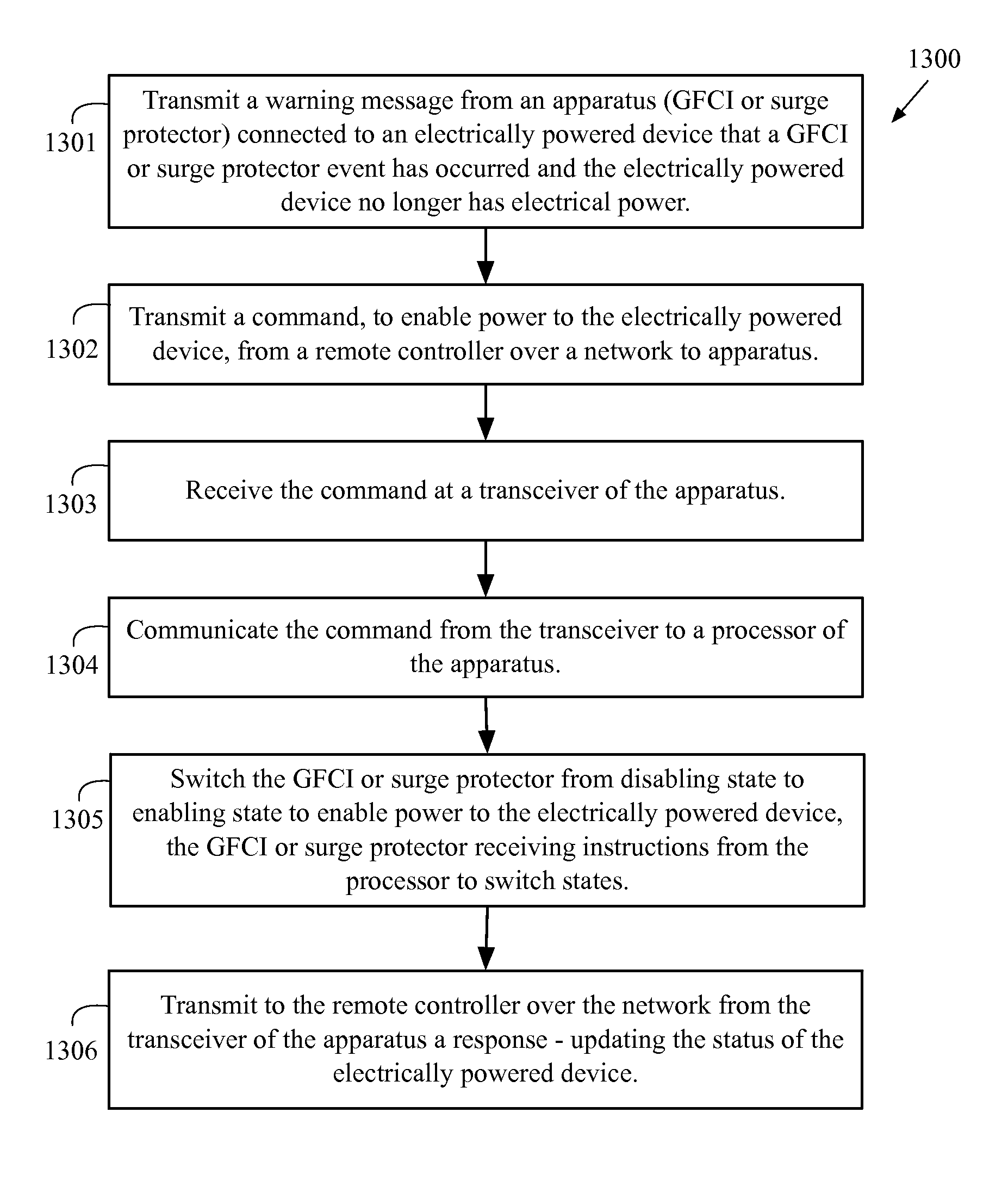
The present invention provides a system and method for controlling power to an electrically powered device with a GFCI or surge protector in a novel and efficient manner. This system allows for effective component power savings, control, and customization for commercial and residential buildings, without the need for rewiring. The features of this invention afford end-users the ability to substantially reduce energy consumption while still utilizing the device's functionality. The system offers remote Wi-Fi management using web-based user interfaces accessible through a home PC, office laptop, or smartphone. Overall, the present invention provides a more efficient and effective solution for controlling power to electrically powered devices.

Problems solved by technology

However, once the circuit is opened, the power is not restored to the vending machine until a reset button is pushed to connect the circuit.
This can lead to the spoilage of goods if the GFCI disablement is not detected for a long period of time.
The prior art fails to disclose a system and method for remotely controlling power to an electrically powered device having a GFCI or surge protector.

Method used


Image

  • Method and apparatus for controlling power to a device
  • Method and apparatus for controlling power to a device
  • Method and apparatus for controlling power to a device

Examples


Embodiment Construction

[0055]A preferred embodiment of an apparatus 10 utilized for controlling power to an electrically powered device is shown in FIGS. 1-3, in the form of an extension cord. The apparatus 10 comprises of at least one controlled socket 11, a casing 12, a plug 13, a switch 14, and a cord 15.

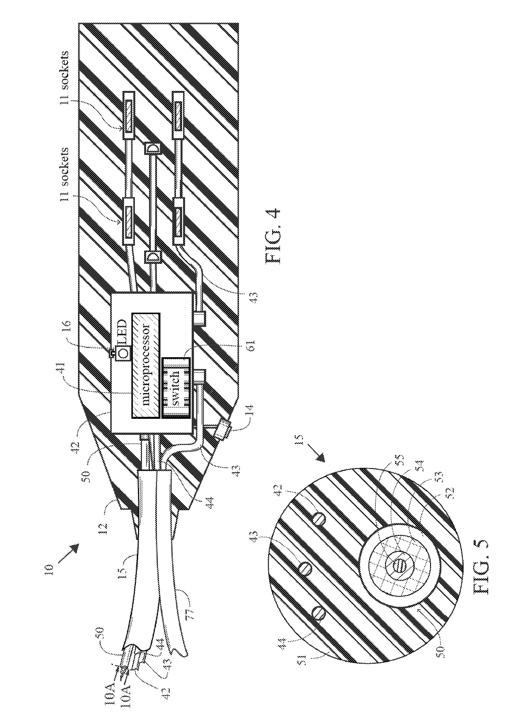
[0056]In FIG. 4, the interior components of the apparatus 10 are shown and in FIG. 6 a circuit block diagram for the apparatus 10 is shown. The apparatus 10 further comprises at least a radio transceiver 50, a microprocessor 41, a switch 61, and a power converter. Additionally, light-emitting diodes (LED) 45 provide status indication.

[0057]The plug 13 is used to receive alternating current (AC) power, and the switch 61 is connected in between the socket 11 and the plug 13.

[0058]The microprocessor 41 receives direct current (DC) power, decodes a control signal from a remote control, such as a handheld device, via the radio transceiver 50, and then controls the switch 61 based on the decoded control sign...


PUM


Abstract

A system and method for remotely controlling power to an electrically powered device having a GFCI or surge protector is disclosed herein. The system preferably comprises an apparatus, an electrically-powered device and a controller. The apparatus preferably comprises a cord, an alternating current outlet socket, an alternating current input plug, a latching relay, a GFCI or surge protector, a processor and a transceiver. The system preferably uses a WiFi communication signal to transmit commands from the remote controller to the apparatus.

Description

CROSS REFERENCES TO RELATED APPLICATIONS[0001]The Present application is a continuation-in-part application of U.S. patent application Ser. No. 13 / 269,531, filed on Oct. 7, 2011, which claims priority to U.S. Provisional Patent Application No. 61 / 391,663, filed on Oct. 10, 2010, and is a continuation-in-part Application of U.S. patent application Ser. No. 13 / 162,564, filed on Jun. 16, 2011, now U.S. Pat. No. 8,093,751, issued on Jan. 10, 2012, which is a continuation application of U.S. patent application Ser. No. 12 / 878,040, filed on Sep. 9, 2010, now U.S. Pat. No. 7,964,989, issued on Jun. 21, 2011, which claims priority to U.S. Provisional Patent Application No. 61 / 361,402, filed on Jul. 3, 2010, all of which are hereby incorporated by reference in their entiretiesSTATEMENT REGARDING FEDERALLY SPONSORED RESEARCH OR DEVELOPMENT[0002]Not ApplicableBACKGROUND OF THE INVENTION[0003]1. Field of the Invention[0004]The present invention generally relates to controlling power to an elect...

Claims


Application Information

Patent Timeline
IPC IPC(8): G06F1/30G06F1/28
CPCG06F1/305G06F1/28Y04S20/242Y04S40/126G06F1/266G06F1/3203H01R13/665H01R13/70H01R25/003H01R27/02G06Q50/06H02J2310/14H02J13/00024H02J13/00026H02J13/00004H02J13/0005H02J3/14Y02B70/30Y02B90/20Y04S20/222Y02B70/3225Y04S20/00
Inventor KRUMMEY, MICHAELYETTER, SCOTT J.
Owner BEST ENERGY REDUCTION TECH
Learn More