
Brake control system for motor vehicles

a technology for controlling systems and brakes, applied in brake control systems, brake components, brake systems, etc., can solve the problems that the driver is generally unable to influence or override the actions of these stability systems, and achieve the effect of ensuring the stability of the vehicl

Active Publication Date: 2015-04-14
ROBERT BOSCH GMBH
View PDF25 Cites 0 Cited by
  • Summary
  • Abstract
  • Description
  • Claims
  • Application Information

AI Technical Summary

Benefits of technology

[0005]The present invention provides the advantage that the stability of the vehicle can be ensured when the assistance system is activated even if the functions of the stability system are not available, or are available to only a limited extent.
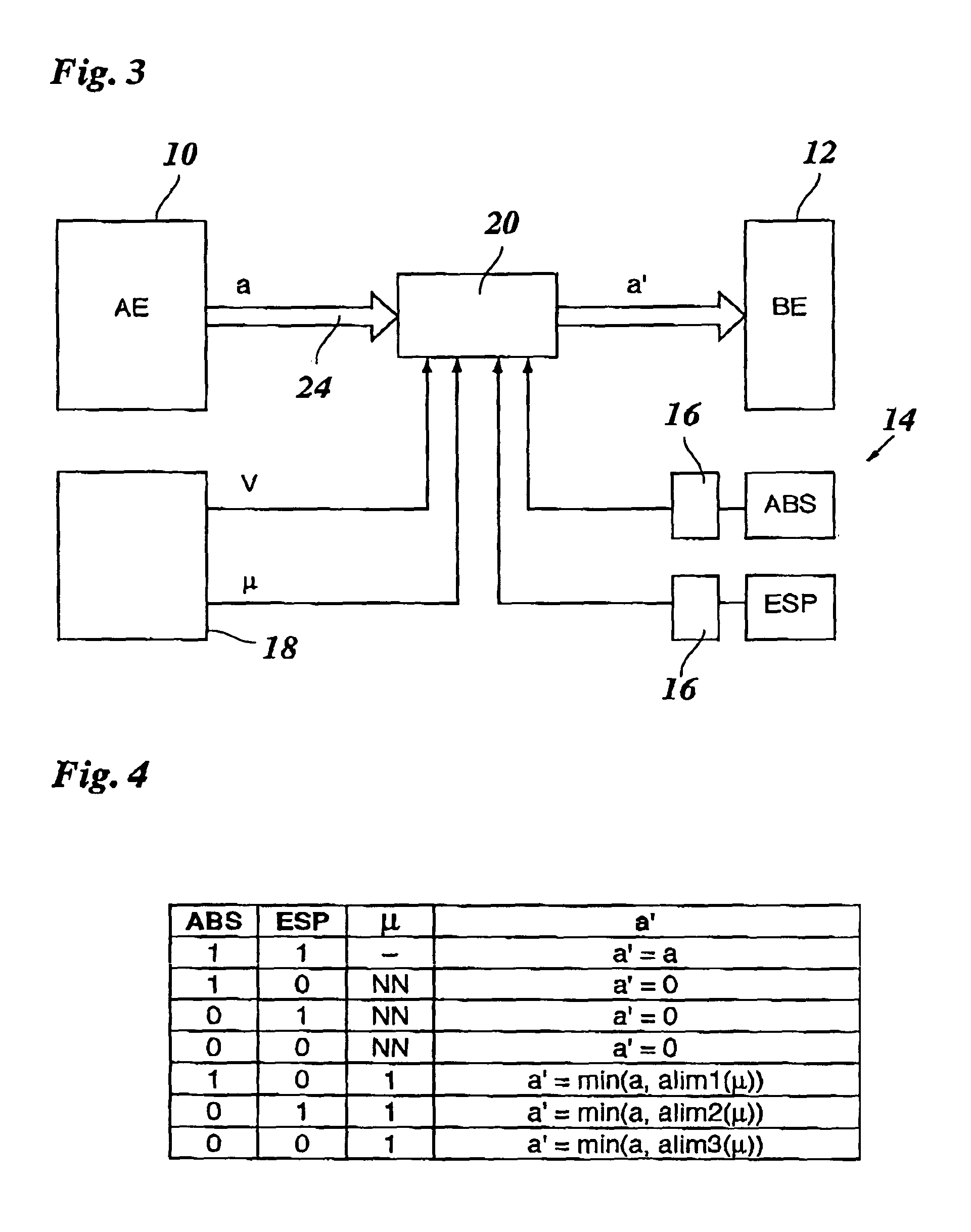
[0007]If the stability system is not fully functional, the control unit thus assures that the braking demand is modified in such a way that the driving stability is nevertheless ensured. In this way, disturbances to comfort, and dangerous situations which could otherwise result due to the lack of vehicle stability, are avoided.

Problems solved by technology

The driver is generally unable to either influence or override the actions of these stability systems.

Method used


Image

  • Brake control system for motor vehicles
  • Brake control system for motor vehicles
  • Brake control system for motor vehicles

Examples


Embodiment Construction

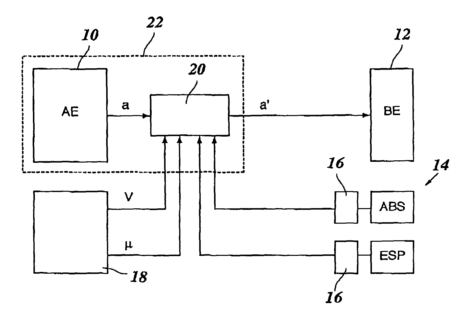
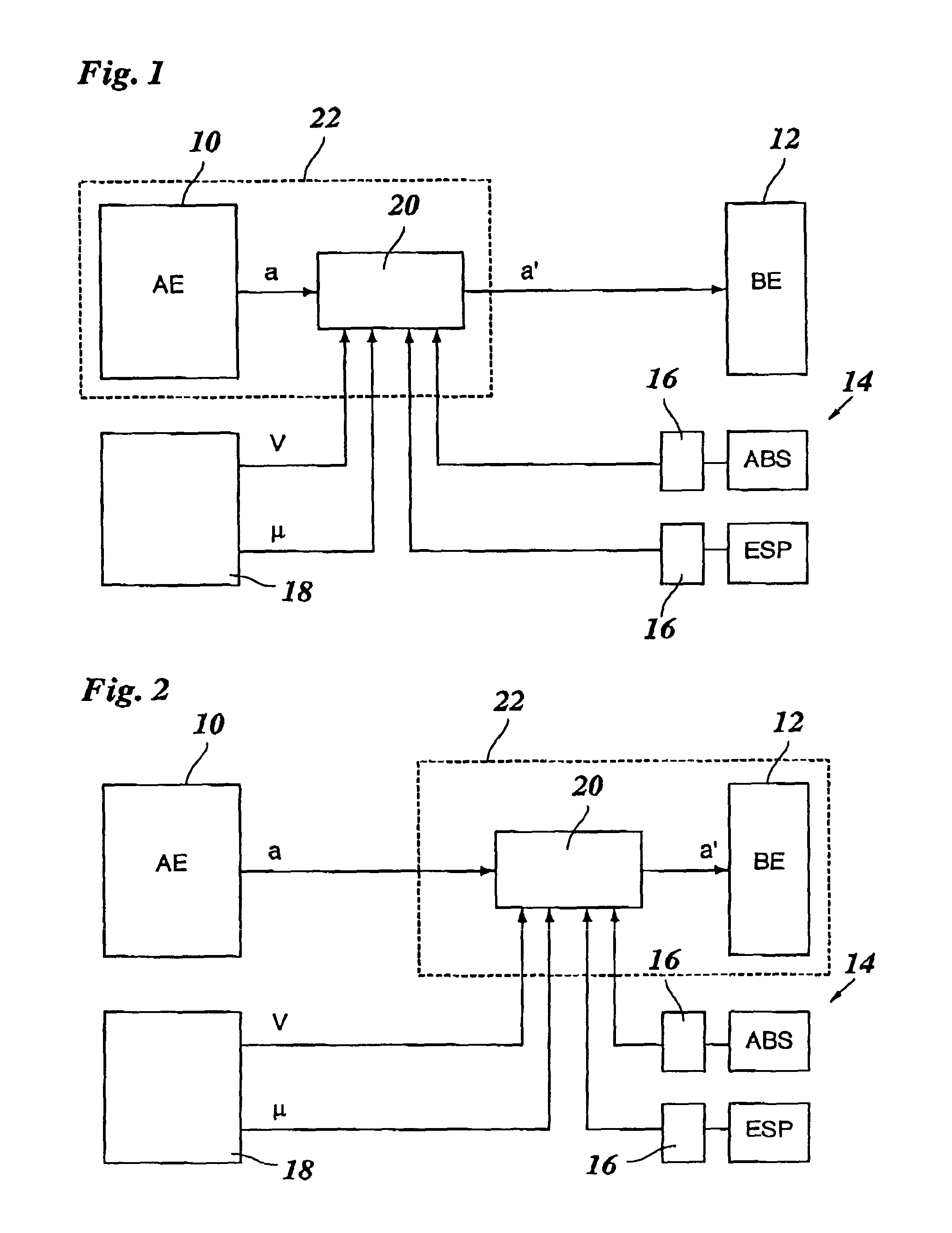
[0013]The brake control system shown in FIG. 1 includes a triggering unit 10 and a braking unit 12 as main components. These units may be separate hardware components, or different program modules of an integrated electronic data-processing device. Triggering unit 10 may be formed, for instance, by an ACC system or any other assistance system which is able to intervene in the brake system of the vehicle, and to this end, to output a braking demand “a” to braking unit 12. Braking unit 12 then controls the braking force at the wheels of the vehicle according to this braking demand a. Braking demand a is thus a signal which quantitatively indicates the intensity of the braking intervention, e.g., in the form of a setpoint braking deceleration, a setpoint braking pressure or the like.

[0014]Also belonging to the brake control system is a stability system 14 which, in the example shown, includes two electronic regulating devices, ABS (anti-lock braking system) and ESP (electronic stabilit...


PUM


Abstract

A brake control system for motor vehicles includes a stability system for stabilizing the vehicle from the standpoint of driving dynamics during braking, a triggering unit for the automatic output of a braking demand as a function of the traffic situation, a braking unit which converts the braking demand into a braking action, and a control unit for modifying the braking demand prior to its implementation as a function of the state of the stability system.

Description

FIELD OF THE INVENTION[0001]The present invention relates to a brake control system for motor vehicles, having a stability system for stabilizing the vehicle during braking.BACKGROUND INFORMATION[0002]For the most part, modern motor vehicles have an electronic stability system, e.g., ABS (anti-lock braking system) and / or ESP (electronic stability program) which provides for stabilization of the vehicle from the standpoint of driving dynamics, e.g., during braking, and thus assists the driver in guiding the vehicle. The driver is generally unable to either influence or override the actions of these stability systems.[0003]On the other hand, there are assistance systems which assist the driver on another level in guiding the vehicle. Examples of such assistance systems are so-called ACC (adaptive cruise control) systems which permit automatic speed control and automatic distance control with respect to the preceding vehicle, warning systems which warn the driver of critical traffic si...

Claims


Application Information

Patent Timeline
Patent Type & Authority Patents(United States)
IPC IPC(8): B60T8/88B60T7/22
CPCB60T8/885B60T2201/02B60T2270/402
Inventor HEINEBRODT, MARTINRANDLER, MARTIN
Owner ROBERT BOSCH GMBH
Learn More