
Surgical instrument

a surgical instrument and clamping surface technology, applied in the field of surgical instruments, can solve the problems of tissue slippage relatively easily from the clamping surface, considerable wear of the cutting instrument, etc., and achieve the effect of improving the cutting action and good and safe operability

Inactive Publication Date: 2015-03-31
ERBE ELEKTROMEDIZIN GMBH
View PDF23 Cites 146 Cited by
  • Summary
  • Abstract
  • Description
  • Claims
  • Application Information

AI Technical Summary

Benefits of technology

[0006]The object of the invention is to provide a surgical instrument of the type specified initially that combines an improved cutting action with good and safe operability.
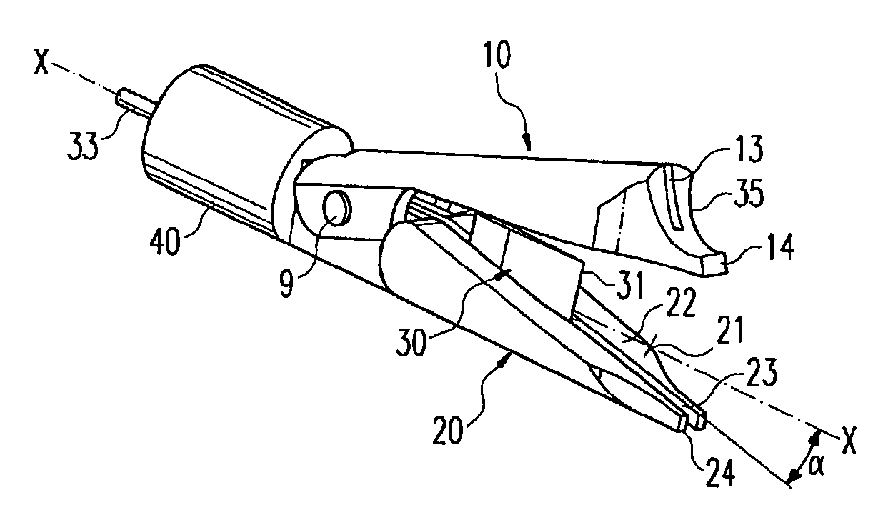
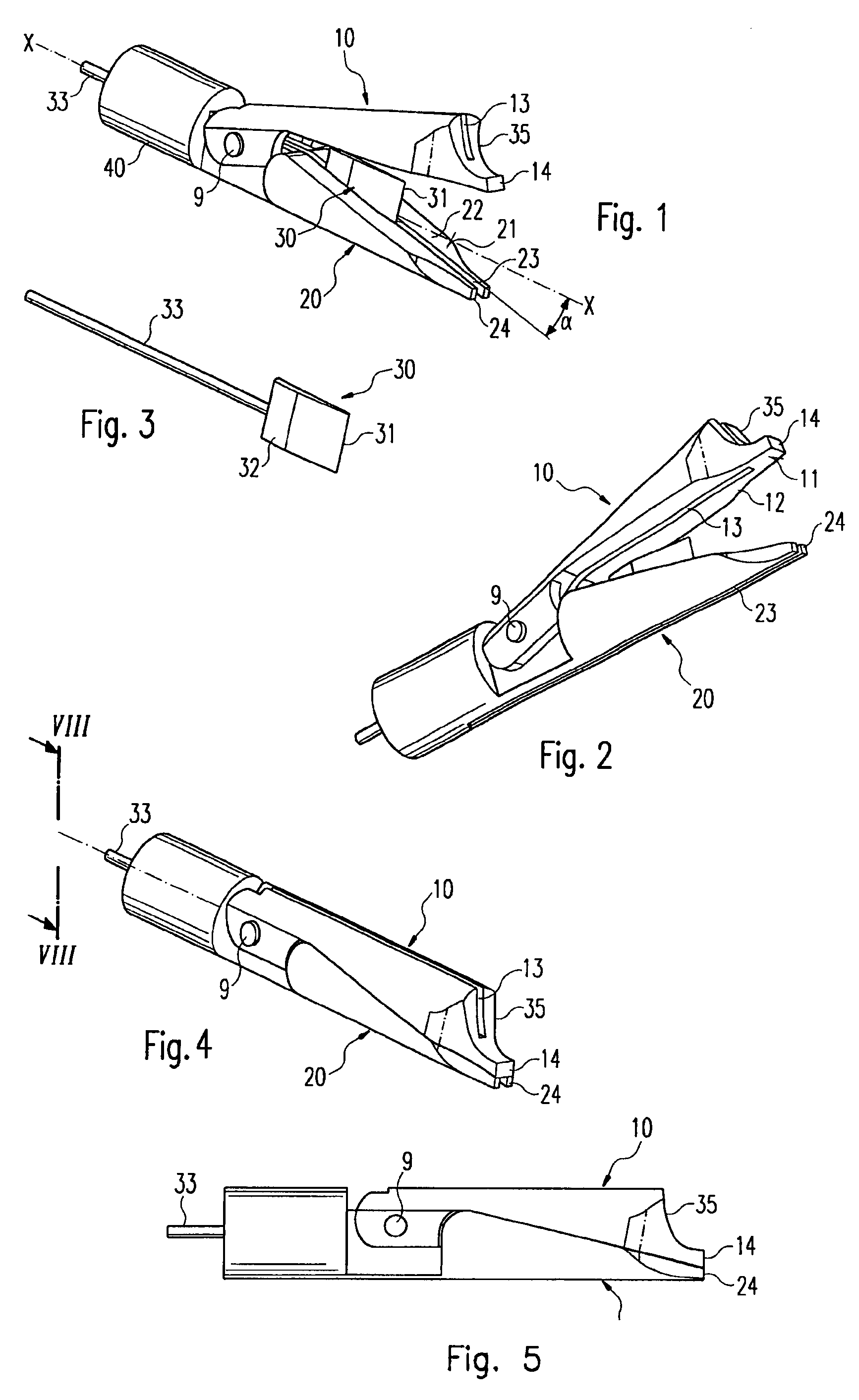
[0008]In the present invention the clamping surfaces do not hold the tissue—as in the state of the art instruments initially specified—in such a way that the cutting device only exerts forces on the tissue in directions that tend to move the gripped tissue out of the grip of the clamping surfaces. Rather, the angular arrangement ensures that at least parts of the cutting force exerted acts in a direction perpendicular to the clamping surfaces and thus the tissue tends to remain securely in the grip of the clamping surfaces. At the same time, good operability of the instrument is achieved since the instrument can be arranged in such a way that, with opened clamping parts, an advance motion for the grasping of tissue occurs substantially in the direction of an angle bisector between the clamping surfaces, which is of great advantage with laparoscopic operations in particular.
[0009]A further advantage of the instrument according to the invention is that the cutting edge of the cutting device on its path through the opening between the clamping surfaces does not continually meet the same section of the tissue, but rather the cut tissue travels over the cutting edge, with the result that, on the one hand, it is cut rather than pressed and, on the other, the cutting edge is used over a larger longitudinal section and thus is worn less.
[0011]Preferably, the cutting edge is inclined at an obtuse angle relative to the cutting direction, which improves the actual cutting action. In addition, the path over which the cutting device must be moved is reduced. This angle of inclination may be constant over the length of the cutting edge relative to the cutting direction or alter with a cutting edge curved like an arc over the latter's length. With such a cutting edge that is curved like an arc, a “soft” first cut may be made, which then becomes a steeper, more forcefully cutting progression of cut.
[0012]Preferably, one of the clamping parts is immovable relative to the cutting direction. As a result, the operator will have a fixed reference point when grasping tissue. In addition, the mechanics for moving the clamping parts are simple.
[0013]Preferably, the surgical instrument is attached at one distal end of a mount to form a tubular shaft instrument for laparoscopic or similar minimally invasive operations. The instrument thus configured handles well. In particular, tissue is easy to grasp and prepare due to the inclination with respect to an axis of the tubular shaft.

Problems solved by technology

The problems with this instrument are considered to be that, on the one hand, there is considerable wear to the cutting instrument while, on the other, the tissue slips relatively easily from the clamping surfaces when being cut through and thus is not cut through completely.

Method used


Image

  • Surgical instrument
  • Surgical instrument
  • Surgical instrument

Examples


Embodiment Construction

[0028]In the following description, the same reference numerals are used for the same and similarly working parts.

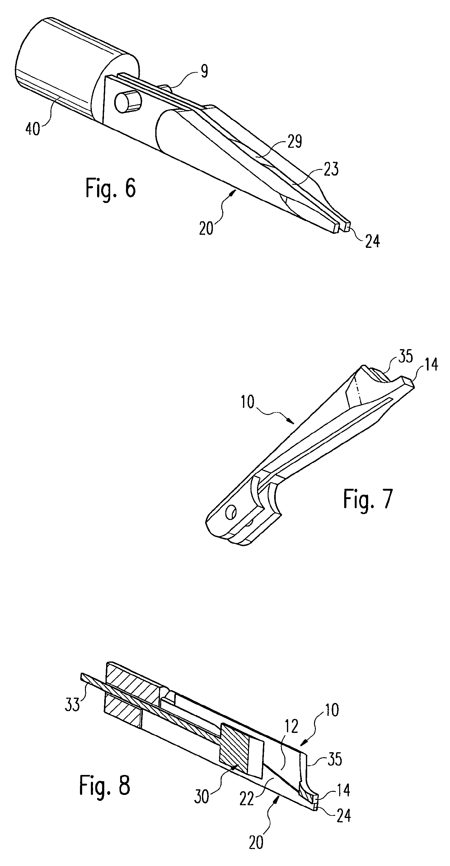
[0029]As shown in FIGS. 1-8, the surgical instrument comprises a first, in the drawings upper, clamping part 10 and a second, in the drawings lower, clamping part 20. Each of the clamping parts 10 and 20 has a clamping surface 11 and 21 respectively, which are fitted in an essentially conventional way with electrodes 12 and 22 respectively. The clamping parts 10 and 20 are connected to each other via an articulated joint 9, wherein the (upper) clamping part 10 has an actuating device, which is familiar in itself and, for the sake of simplicity, has not been depicted in the figures.

[0030]When tissue is clamped between the two clamping surfaces 11 and 21, a HF current may be passed via the electrodes 12, 22 into the tissue for coagulating the same.

[0031]The upper clamping part 10 and the lower clamping part 20 each have a groove 13 and 23 respectively, in which a cutting d...


PUM


Abstract

Surgical instruments are provided for performing laparoscopic or similar minimally invasive operations, including two clamping parts, which can move towards one another and which have clamping surfaces for gripping tissue when they are closed. A cutting device has a cutting edge that, in a cutting direction, can be displaced relative to the clamping parts for cutting the gripped tissue. In such an instrument the cutting direction extends at an acute angle to the clamping surfaces when they are closed.

Description

CROSS-REFERENCE TO RELATED APPLICATIONS[0001]This application is a Section 371 of International Application No. PCT / EP2005 / 007559, filed on Jul. 12, 2005, which was published in the German language on Mar. 2, 2006, under International Publication No. WO 2006 / 021269 A1 and the disclosure of which is incorporated herein by reference. International Application No. PCT / EP2005 / 007559 claims priority to German Patent Application No. 10 2004 040959.5, filed Aug. 24, 2004.BACKGROUND OF THE INVENTION[0002]The invention concerns a surgical instrument with at least two clamping parts and a cutting device for use, in particular, in laparoscopic or similar minimally invasive operations.[0003]Instruments of this type are used to cut, prepare and coagulate tissue, in particular in minimally invasive surgery, e.g. laparoscopy. A requirement of instruments of this type is that tissue can be safely gripped in a simple manner and then be cut through equally safely. At the same time, it is also importa...

Claims


Application Information

Patent Timeline
Patent Type & Authority Patents(United States)
IPC IPC(8): A61B18/14
CPCA61B18/1445A61B2018/1412A61B2018/1455
Inventor BRODBECK, ACHIMHAFNER, DIETER
Owner ERBE ELEKTROMEDIZIN GMBH
Learn More