
Tampon insertion device for improved control and pledget placement

a technology of insertion device and pledget, which is applied in the field of tampon applicator assembly, can solve the problems of difficult grip and/or control, hinder the proper and comfortable delivery of pledget, and user often applies excessive gripping force on the barrel, etc., and achieves the effect of convenient grip and control, and convenient us

Inactive Publication Date: 2015-02-24
EDGEWELL PERSONAL CARE BRANDS LLC
View PDF47 Cites 12 Cited by
  • Summary
  • Abstract
  • Description
  • Claims
  • Application Information

AI Technical Summary

Benefits of technology

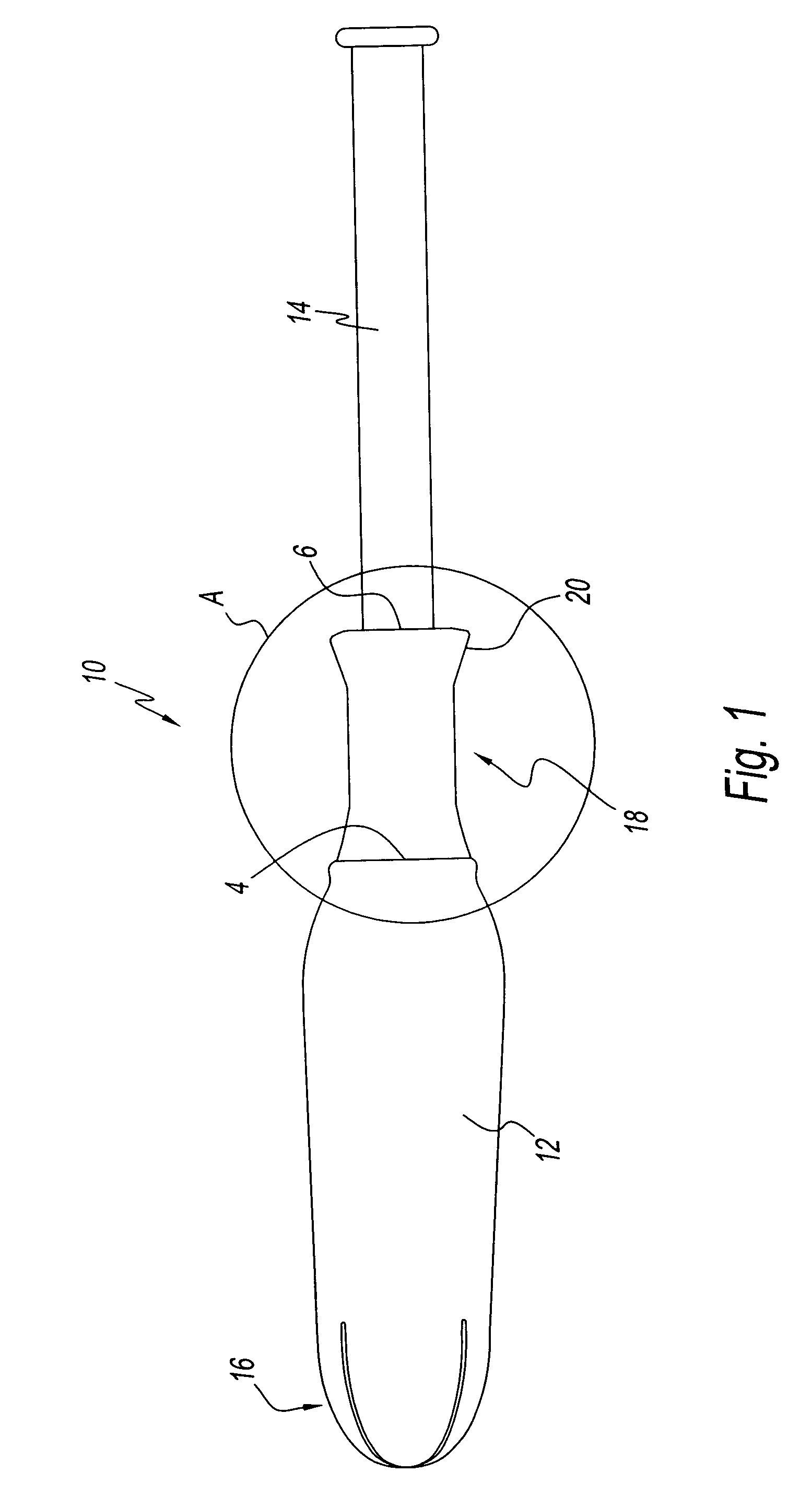
The present patent provides a tampon applicator assembly that is easy to use and control during insertion and removal of the applicator. It also provides improved comfort to the user as a result of its unique fingergrip design.

Problems solved by technology

Accordingly, an assembly that is difficult to grip and / or control can hinder proper and comfortable delivery of the pledget.
Another problem associated with an assembly that is difficult to grip and / or control is that the user often applies excessive gripping force on the barrel to compensate for the lack of grippability.
This excessive force may partially deform and damage the barrel and / or plunger, thereby distorting the assembly and obstructing the normal pathway of the pledget therefrom.
As a result, the user may be required to apply a significant amount or excess force to eject the pledget from the assembly, which may result in discomfort to the user.

Method used


Image

  • Tampon insertion device for improved control and pledget placement
  • Tampon insertion device for improved control and pledget placement
  • Tampon insertion device for improved control and pledget placement

Examples


examples

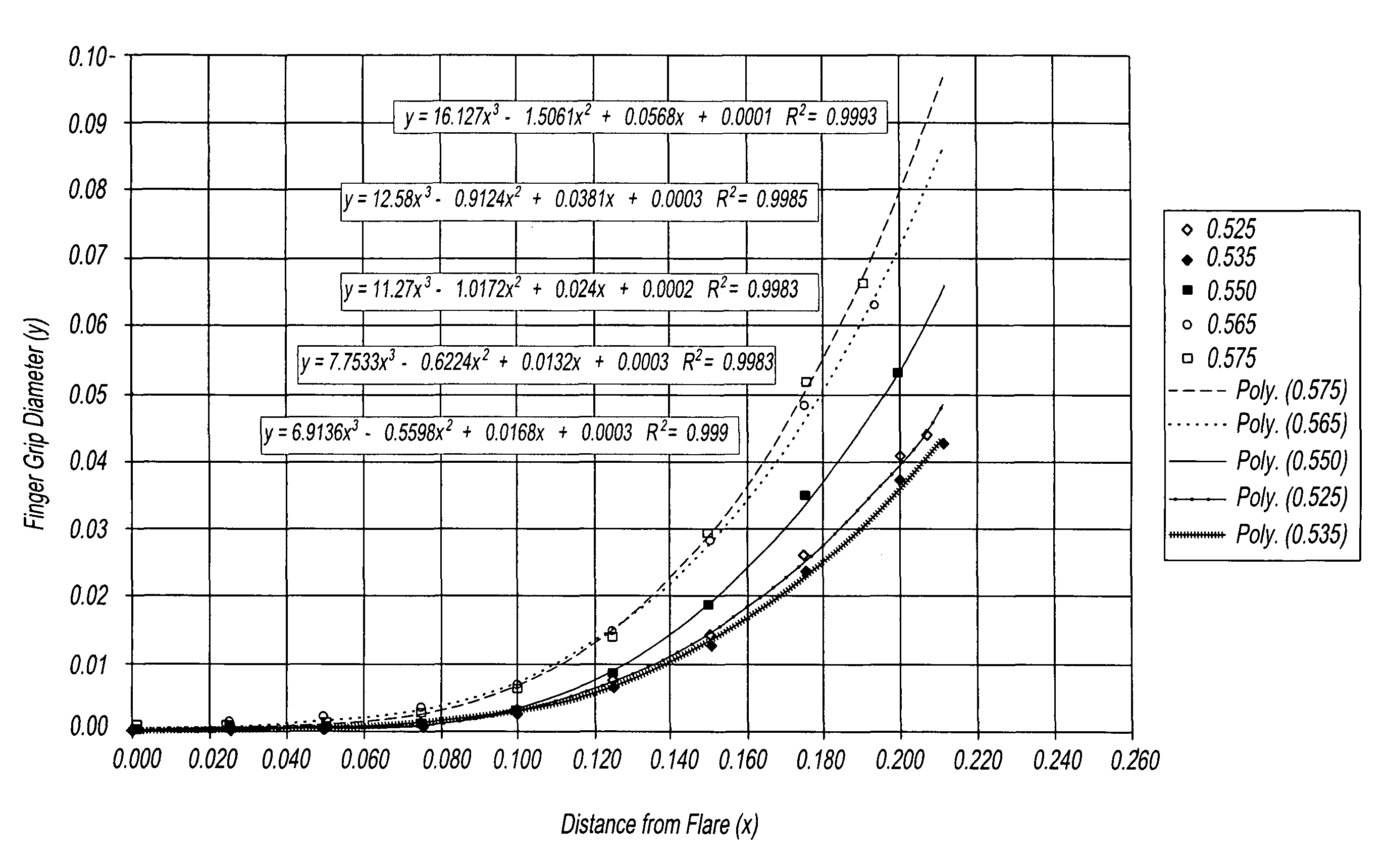
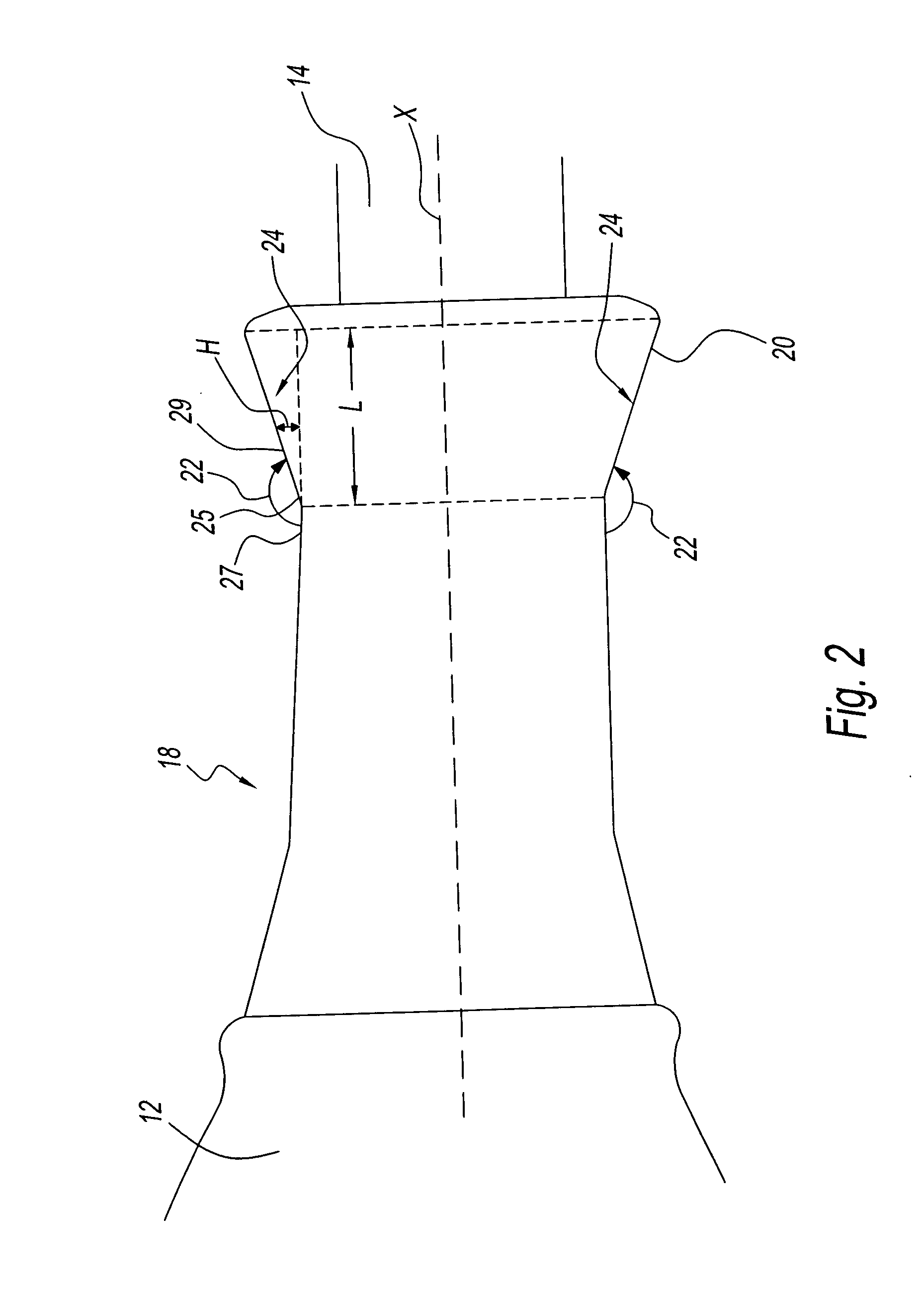
[0055]Tampon applicators of the Ultra sort having a flared fingergrip according to the present disclosure with a target flare diameter were formed. The flared portion was measured, where y is the incremental increase in height H of the flare at distance x along the length of the flare. The measurements are set forth below in Table 1.

[0056]

TABLE 1Flared Fingergrip measurements - Ultra TamponTarget Flare Diameter (inches)Distance0.5250.5350.5500.5650.575(x axis)Y axis0.0000.00000.00000.00000.00000.00000.0250.00070.00070.00040.00120.00090.0500.00100.00110.00100.00190.00150.0750.00100.00110.00100.00370.00310.1000.00290.00300.00350.00690.00630.1250.00670.00690.00850.01440.01470.1500.01430.01320.01870.02830.02930.1750.02620.02370.03540.04820.05170.1900.06630.1930.06300.2000.04100.03740.05370.2070.04400.2110.0430Flare angle156°149°145°141°139°

[0057]Referring to FIG. 10, the above measurements were plotted on a graph, which details the curvature of the flare of each tampon applicator. Addit...


PUM


Abstract

A tampon applicator assembly has a barrel with a fingergrip. The fingergrip has one or more flared portions and / or one or more rib-like or ring-like gripping structures. A tampon applicator fingergrip includes one or more flared portions having a flare angle between about 139° and about 156° and a curve represented by an equation range of y=16.127x3−1.5061x2+0.0568x+0.0001 to y=6.9136x3−0.5598x2+0.0168x+0.0003, where y is an incremental increase in a height of the curve at a distance along a length of the curve.

Description

CROSS REFERENCE TO RELATED PATENT APPLICATIONS[0001]This application claims the benefit of U.S. Provisional Application Ser. No. 60 / 835,638 filed Aug. 4, 2006 entitled “Tampon Insertion Device for Improved Control and Pledget Placement,” now pending. The aforementioned application is hereby incorporated herein by reference in its entirety.BACKGROUND OF THE INVENTION[0002]1. Field of the Invention[0003]The present disclosure relates generally to a tampon applicator assembly. More particularly, the present disclosure relates to an improved tampon applicator assembly that improves user control of the tampon applicator and pledget placement in the body.[0004]2. Description of Related Art[0005]A tampon applicator assembly is used to inject an absorbent or hygienic material, known as a tampon pledget, into a vaginal cavity. Commercial tampon applicator assemblies typically have a barrel and a plunger used to expel a pledget housed in the barrel.[0006]The use of such assemblies requires a ...

Claims


Application Information

Patent Timeline
Patent Type & Authority Patents(United States)
IPC IPC(8): A61F13/26A61F13/32
CPCA61F13/26A61F13/2031A61F13/20
Inventor JORGENSEN, ROBERTEDGETT, KEITHDOUGHERTY, JR., EUGENE P.
Owner EDGEWELL PERSONAL CARE BRANDS LLC
Learn More