
Adjustable prosthetic limb socket

a prosthetic limb and socket technology, applied in the field of adjustable prosthetic limb sockets, can solve the problems of cyclical and greatly affected, affecting the fit of the proper amount of volumetric sockets, and compromising the hydrostatic weight bearing and skeletal control characteristics of the sockets, so as to achieve adequate control and comfort the effect of weight bearing

Active Publication Date: 2015-02-03
CJ SOCKET TECH
View PDF31 Cites 4 Cited by
  • Summary
  • Abstract
  • Description
  • Claims
  • Application Information

AI Technical Summary

Benefits of technology

The present invention has a comfortable and stable shank for controlling the prosthesis in space. It also allows for unprecedented volume control using a flexible support or garment.

Problems solved by technology

Maintaining a proper amount of volumetric socket fit is challenging and often problematic due to the tendencies of the residual limb to change in volume and the soft tissue to displace under load.
Daily volume loss is generally replenished during non-wearing times i.e. sleep, and is cyclical and greatly affected by activity.
As the residual limb loses volume the hydrostatic weight bearing and skeletal control characteristics of the socket are compromised.
This leads to painful, limiting and / or injurious increases in socket pressure as well as energy wasting and destabilizing excessive motion between the socket and skeletal segments of the residual limb.
As the user attempts to control the prosthesis in space by employing their proximal musculature, relative motion between the residual limb and prosthesis causes forces which accelerate and impact the residual limb.
These forces can be compressive, or cause strain or shear, which in turn increase localized pressure and / or tension on the residual limb.
This commonly results in pain and injury as well as increased energy use and premature fatigue.
As a result, traditional sockets tend not to function well when changes in the residual limb's volume, shape or size occur.
This is a common occurrence and has not been addressed effectively.
This shape can cause difficulty in donning the socket because the socket pushes past the larger distal dimension to be secured to the smaller proximal socket dimension

Method used


Image

  • Adjustable prosthetic limb socket
  • Adjustable prosthetic limb socket
  • Adjustable prosthetic limb socket

Examples


Embodiment Construction

[0035]A description of preferred embodiments of the invention follows.

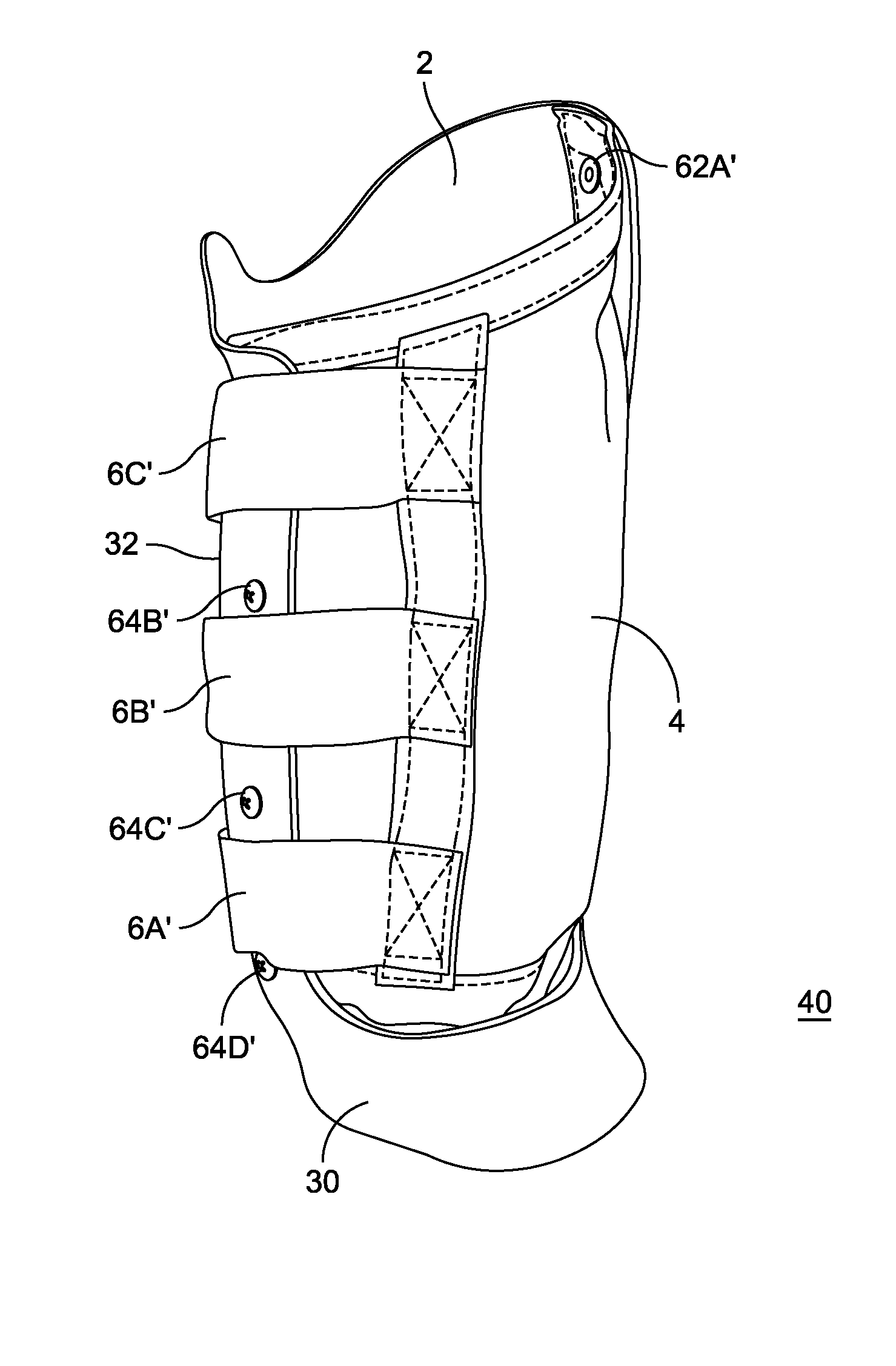
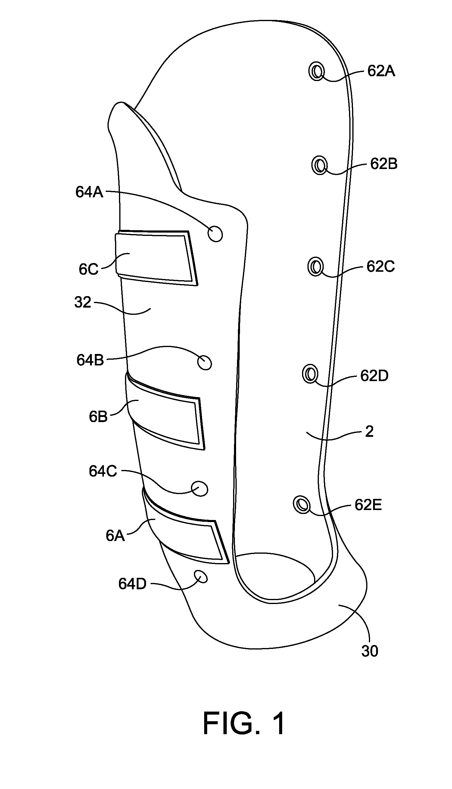
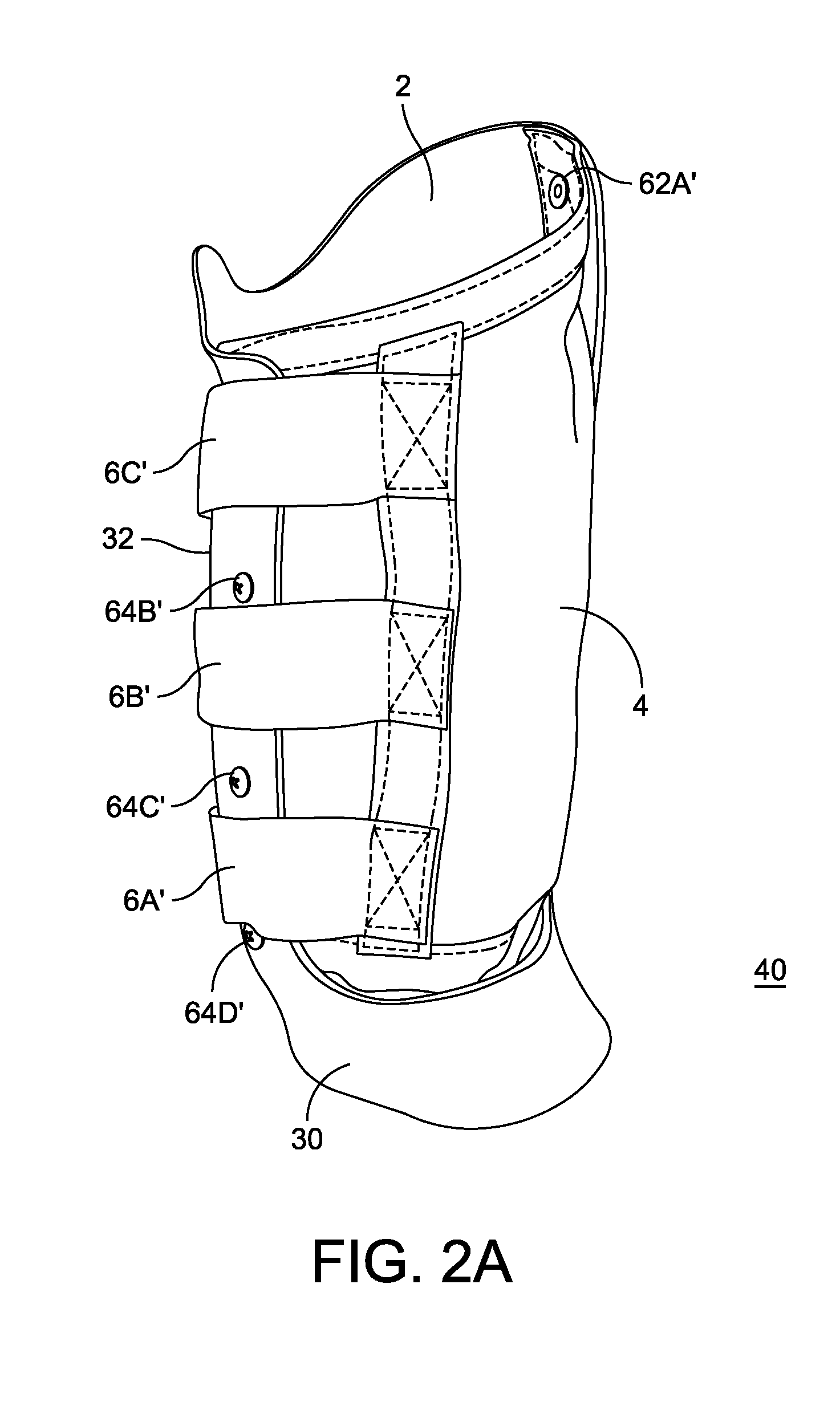
[0036]The present invention relates to a new socket design that is stable, comfortable, and allows for volumetric changes in the residual limb. In particular, the present invention relates to a socket that has a rigid support that conforms to a portion of the residual limb, and a sail (also referred to herein as a “flexible support”) which is a strong, flexible and preferably non-elastic garment that covers the balance of the circumference of the residual limb. The socket system of the present invention also includes a means for securing the sail e.g. with a closure system, and an attachment at the base of the rigid support for attaching the prosthetic device.

[0037]Unlike traditional sockets that include a rigid or semi-rigid socket that conforms to most or all of the outer circumference of the residual limb, the rigid support of the present invention is a partial support. More specifically, in an aspect, the rigi...


PUM

PropertyMeasurementUnit
widthaaaaaaaaaa
widthaaaaaaaaaa
tensile strengthaaaaaaaaaa

Abstract

The present relates to an adjustable prosthetic limb socket system having a partial rigid support, a non-elastic, flexible support and adjustment means. The adjustable socket system of the present invention can be used for several types of amputations including transfemoral amputations, transtibial amputations, transhumeral amputations, transradial amputations, and other types of amputations. The present invention further includes kits having the adjustable prosthetic limb socket system, as well as methods of making the adjustable prosthetic limb socket system. Methods of using the socket system are further encompassed by the present invention.

Description

RELATED APPLICATIONS[0001]This application claims the benefit of U.S. Provisional Application No. 61 / 373,258, filed Aug. 12, 2010 entitled, “Adjustable Prosthetic Limb Socket” by Keith D. Cornell.[0002]The entire teachings of the above application(s) are incorporated herein by reference.BACKGROUND OF THE INVENTION[0003]A prosthetic device for an arm or leg is traditionally worn by inserting the residual limb into a rigid or semi-rigid socket. Traditional sockets are designed as a 360 degree container surrounding the entire residual limb. Sockets generally perform at least two broad functions. Firstly, the traditional socket is designed to allow comfortable weight bearing and prevent soft tissue damage as weight pressures are applied to the residual limb via the prosthetic socket. This is generally achieved with a combination of skeletal weight bearing and hydraulic lift created as the residual limb fluids are pressurized in the socket. Secondly, the traditional socket also functions...

Claims


Application Information

Patent Timeline
Patent Type & Authority Patents(United States)
IPC IPC(8): A61F2/78A61F2/80A61F2/50A61F2/76
CPCA61F2/80A61F2/78A61F2002/5026A61F2002/5027A61F2002/5052A61F2002/5056A61F2/76A61F2002/7818A61F2002/805A61F2002/5053A61F2002/7881A61F2002/802A61F2210/0071A61F2/7812Y10T29/4998A61F2002/7862A61F2002/7893
Inventor CORNELL, KEITH D.
Owner CJ SOCKET TECH
Learn More