Light source apparatus and image display apparatus
a technology of light source apparatus and image display device, which is applied in the direction of lighting and heating apparatus, picture reproducers using projection devices, instruments, etc., can solve the problems of difficult to obtain high-output red light with the conventional light source apparatus, and difficulty in obtaining high-output red ligh
- Summary
- Abstract
- Description
- Claims
- Application Information
AI Technical Summary
Benefits of technology
Problems solved by technology
Method used
Image
Examples
embodiment 1
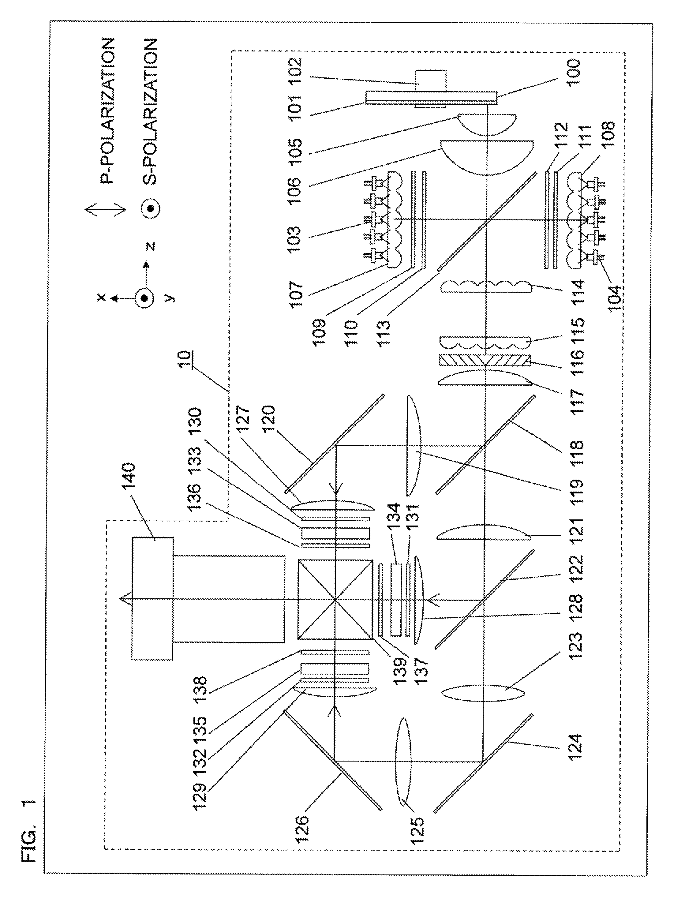
[0047]FIG. 1 shows a structural diagram of a light source apparatus and an image display apparatus using the light source apparatus according to a first embodiment.
[0048]The structure of an image display apparatus 10 according to the present embodiment is as follows.
[0049]A substrate 100 is a circular piece of plane parallel glass, and is coated with dichroic coating on the surface on one side thereof, the dichroic coating reflecting light in the entire visible light range with a high efficiency. Additionally, a phosphor 101 is applied as a thin film further to the dichroic coating, and emits fluorescence having wavelengths of green as a main wavelength region of fluorescence. The substrate 100 is attached to rotation means 102 so as to be controlled to rotate. With xyz coordinate axes defined as shown in FIG. 1, the substrate 100 rotates about a rotating shaft parallel to the z-axis. The number of rotations of the substrate 100 is not particularly limited, but is preferably 1000 rp...
embodiment 2
[0080]FIG. 6 shows a structural diagram of a light source apparatus and an image display apparatus using the light source apparatus according to a second embodiment. Some of the components of the present embodiment are the same as those of the first embodiment, and therefore are not described here.
[0081]The structure of an image display apparatus 20 according to the present embodiment is as follows.
[0082]A substrate 200, a phosphor 201, and rotation means 202 employed in the present embodiment are the same as those of the first embodiment. A phosphor is applied annularly about the rotating shaft, of the substrate 200, parallel to the x-axis.
[0083]An excitation light source 203, a collimating lens array 207, a red laser light source 204, and a collimating lens array 208 are also the same as those of the first embodiment. The entirety of the collimated blue laser light, however, is adjusted to be P-polarized light, passes through a diffusion plate 209, and is subsequently made inciden...
embodiment 3
[0098]FIG. 9 shows a structural diagram of a light source apparatus and an image display apparatus using the light source apparatus according to a third embodiment. Some of the components of the present embodiment are the same as those of the first embodiment, and therefore are not described here.
[0099]The structure of an image display apparatus 30 according to the present embodiment is as follows.
[0100]A substrate 300, a phosphor 301, and rotation means 302 employed in the present embodiment are the same as those of the first embodiment. A yellow phosphor is applied annularly about the rotating shaft, of the substrate 300, parallel to the z-axis. The yellow phosphor may be a YAG (yttrium-aluminum-garnet) phosphor material, for example.
[0101]An excitation light source 303 and a collimating lens array 307 are also the same as those of the first embodiment. The entirety of the collimated blue laser light is adjusted to be S-polarized light, passes through a diffusion plate 310, and is...
PUM
 Abstract
Description
Claims
Application Information
 - R&D
- Intellectual Property
- Life Sciences
- Materials
- Tech Scout
- Unparalleled Data Quality
- Higher Quality Content
- 60% Fewer Hallucinations
Browse by: Latest US Patents, China's latest patents, Technical Efficacy Thesaurus, Application Domain, Technology Topic, Popular Technical Reports.
© 2025 PatSnap. All rights reserved.Legal|Privacy policy|Modern Slavery Act Transparency Statement|Sitemap|About US| Contact US: help@patsnap.com


