
Jump rope device comprising a removably-connected cable

Active Publication Date: 2014-12-16
CROSSROPE
View PDF95 Cites 14 Cited by
  • Summary
  • Abstract
  • Description
  • Claims
  • Application Information

AI Technical Summary

Benefits of technology

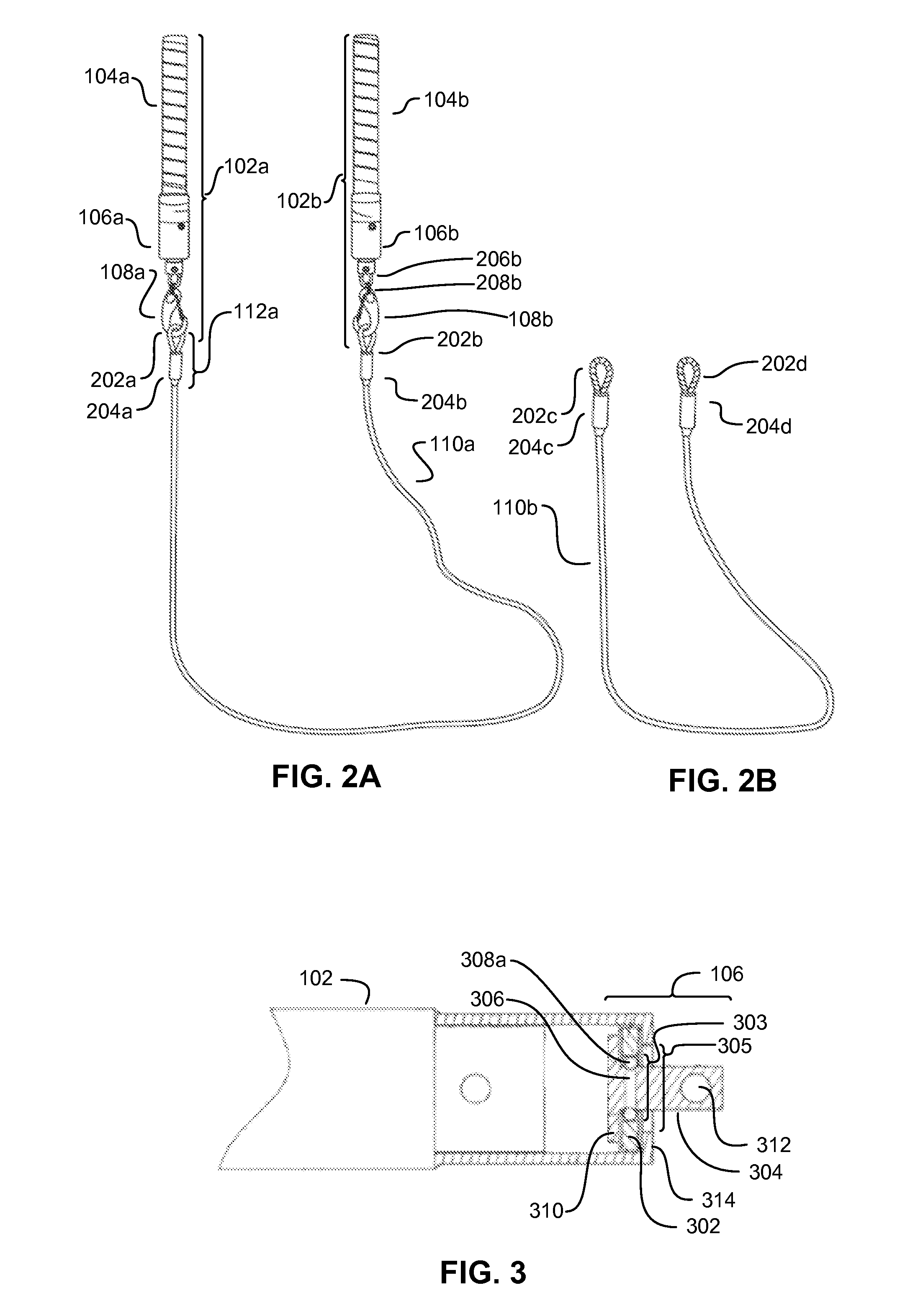
The patent text describes devices that allow for quick and easy interchanging of cables from handles. These handles can be made from various materials like wood or aluminum and are securely attached to a housing that encases a ball bearing assembly with a protruding joint pin. The cable is made of polyvinyl chloride coated galvanized steel and is formed into loops and secured by swaged aluminum collars at each end. The attached cable is easily detached and replaced with another cable by depressing the spring gate portion of the spring gate snap hook and removing the loop portion in order to free the handles. Overall, these devices provide a simple and efficient way to switch between cables quickly and easily.

Problems solved by technology

It reduces the equipment needed to successfully exercise.
However, the effectiveness, ease of adjustment, and scope of scalability of these adjustments has not been fully realized.
However, this design results in handles that are awkward to hold and make jumping rope more difficult because of the number of ropes that have to pass beneath a jumper's feet and that could get caught.
However, this design limits the potential weight of the rope because excessive centrifugal force while jumping rope could unexpectedly dislodge the ball bearing from the rope.
However, this is an ineffective method to vary resistance due to the awkward shape of the rope structure where one end of the center section can hit the ground before the other end does.
This results in the rope bouncing up to hit the jumper's foot or leg.
Additionally, this rope shape does not give the jumper the ability to perform any arm crossing or side-to-side rope jumping skills because the center section obstructs the performance of these types of motion.
However, this design limits the variety and variability of weighted configurations and the composite jump rope weight does not change, just the positioning of the weight.
Exclusion of a means to alter the mass of the jump rope limits the functionality and versatility of the jump rope.
Although this provides a method of increasing the mass of the rope, such designs bend easily and in an unpredictable manner, resulting in an inconsistent and inefficient motions and thus, inefficient workouts.
When a jump rope is used in such a manner, the design of the attachment point of the rope to the handle is critical.
The radial bearing orientation, however, is not optimal for any hand crossing jump rope motions.
This results in a lack of uniformity in the mass distribution of the rope.
Such uneven mass distribution yields an awkward feel and operation, resulting in less efficient workouts and an increased learning curve for novice users.
Quality jump ropes that meet these needs tend to be very expensive.
For a jump rope user who wants to perform multiple types of jump rope exercises and workouts it can be expensive to purchase multiple jump ropes.
An additional problem for consumers is that heavy jump ropes traditionally have been constructed of materials that are prone to breakage, particularly at the interface between the handle and the rope.

Method used


Image

  • Jump rope device comprising a removably-connected cable
  • Jump rope device comprising a removably-connected cable
  • Jump rope device comprising a removably-connected cable

Examples


Embodiment Construction

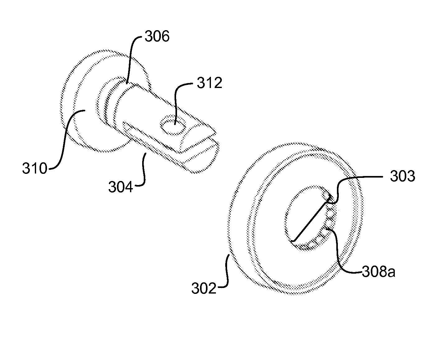
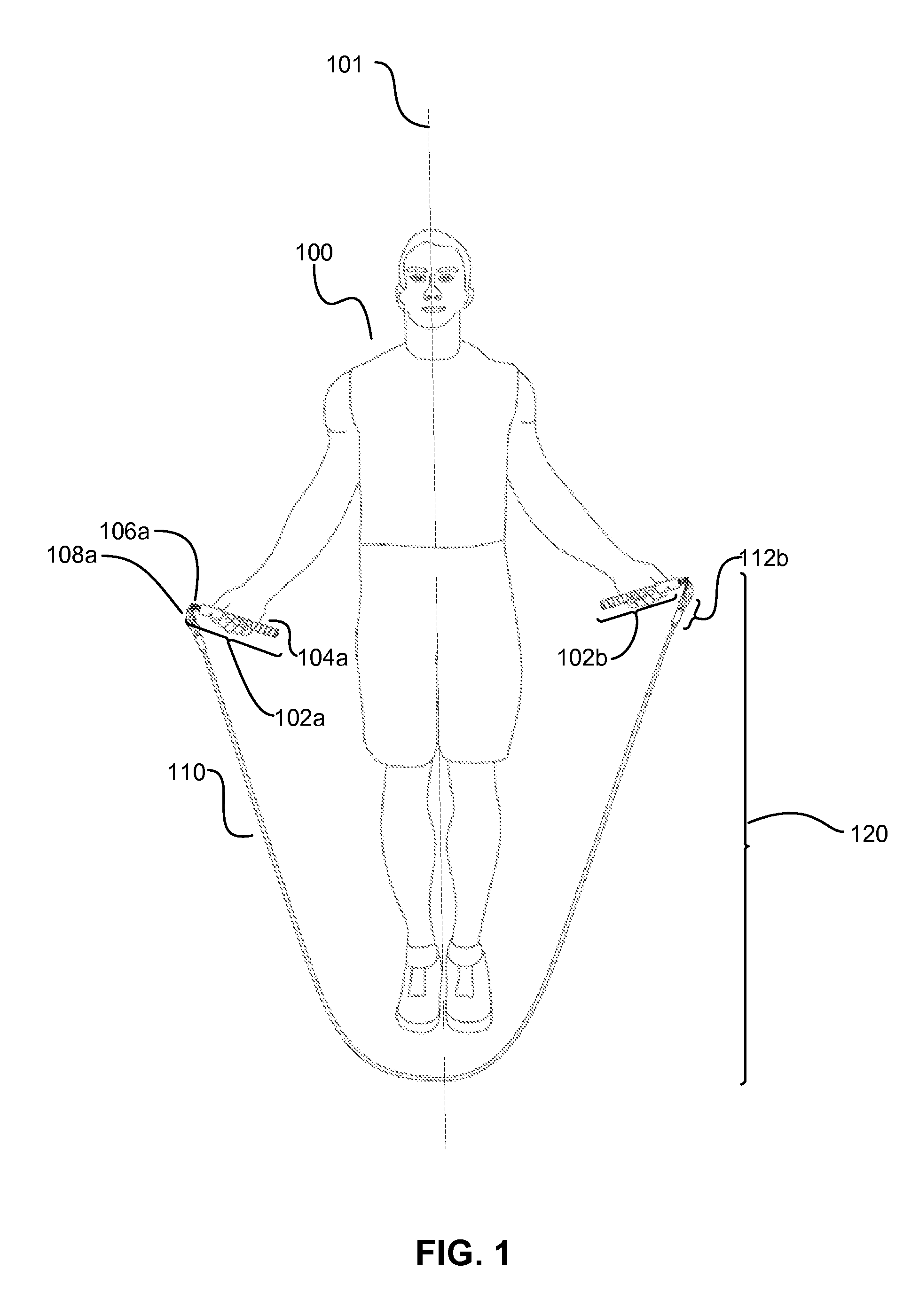
[0047]The present disclosure is directed to jump rope devices which allow for the quick and easy interchanging of a cable of varying weight and length from handles configured to provide smooth rotation of such cables at both low and high speeds. Devices in accordance with the disclosure may comprise a ball bearing assembly configured to facilitate 360-degree rotation of the cable.

[0048]Jump rope devices in accordance with the present disclosure facilitate a variety of traditional as well as modern jump rope-based exercises. Such exercises include: basic bounce step, the alternate foot step, criss cross, side rope swings, single- and double-leg high knee exercises, double unders, run skipping, and the “Ali shuffle.”

[0049]Referring to FIG. 1, a front view of a jump rope 120 being utilized by a user 100, in accordance with an aspect of the present disclosure, is shown.

[0050]Hereinafter, an “inner” portion of an element refers to a portion of an element which is closer to the sagittal p...


PUM


Abstract

Jump rope devices which allow for the quick and easy interchanging of a cable of varying weight and length from handles configured to provide smooth rotation of such cables at both low and high speeds are disclosed. Devices in accordance with the disclosure may comprise a ball bearing assembly configured to facilitate 360-degree rotation of the cable. In an aspect, the handle of such jump rope devices is comprised of a ball bearing portion which enables both speed of rotational movement for a plurality of relatively lighter cables, and strength and durability for a plurality of relatively heavier cables. Handles may further comprise a snap hook assembly configured to facilitate rapid interchanging of cables.

Description

CROSS-REFERENCE TO RELATED APPLICATION[0001]This application claims the benefit of U.S. Provisional Patent Application No. 61 / 578,889, filed Dec. 22, 2011, and entitled “Interchangeable Cable Jump Rope System,” the entire contents of which are incorporated herein by reference.FIELD OF THE DISCLOSURE[0002]The present disclosure relates to exercise equipment and more particularly to jump rope devices.BACKGROUND[0003]Jumping rope has been a popular children's activity since the Middle Ages. Since the 1970's, it has come into the mainstream as a staple of many of the most popular exercise regimes. For example, jumping rope is an essential part of the CrossFit exercise program (available from CrossFit, Inc. of Washington, D.C.). More than 4,000 gyms offer CrossFit classes and hundreds of thousands of people a year follow the program.[0004]Jumping rope has long been a popular exercise due to its health benefits in aerobic and anaerobic training, as well as the enjoyment in performing fun,...

Claims


Application Information

Patent Timeline
IPC IPC(8): A63B21/00A63B5/20
CPCA63B5/20A63B2210/50
Inventor HUNT, DAVID
Owner CROSSROPE
Learn More