
Radiographic system and radiographic image generating method

a radiographic image and radiographic system technology, applied in the direction of material analysis using wave/particle radiation, instruments, applications, etc., can solve the problems of reducing the ability of x-ray absorption, difficult to obtain the inability to acquire an adequate contrast of an image, so as to reduce the burden of the subject, and reduce the effect of density irregularities

Inactive Publication Date: 2014-12-02
FUJIFILM CORP
View PDF11 Cites 35 Cited by
  • Summary
  • Abstract
  • Description
  • Claims
  • Application Information

AI Technical Summary

Benefits of technology

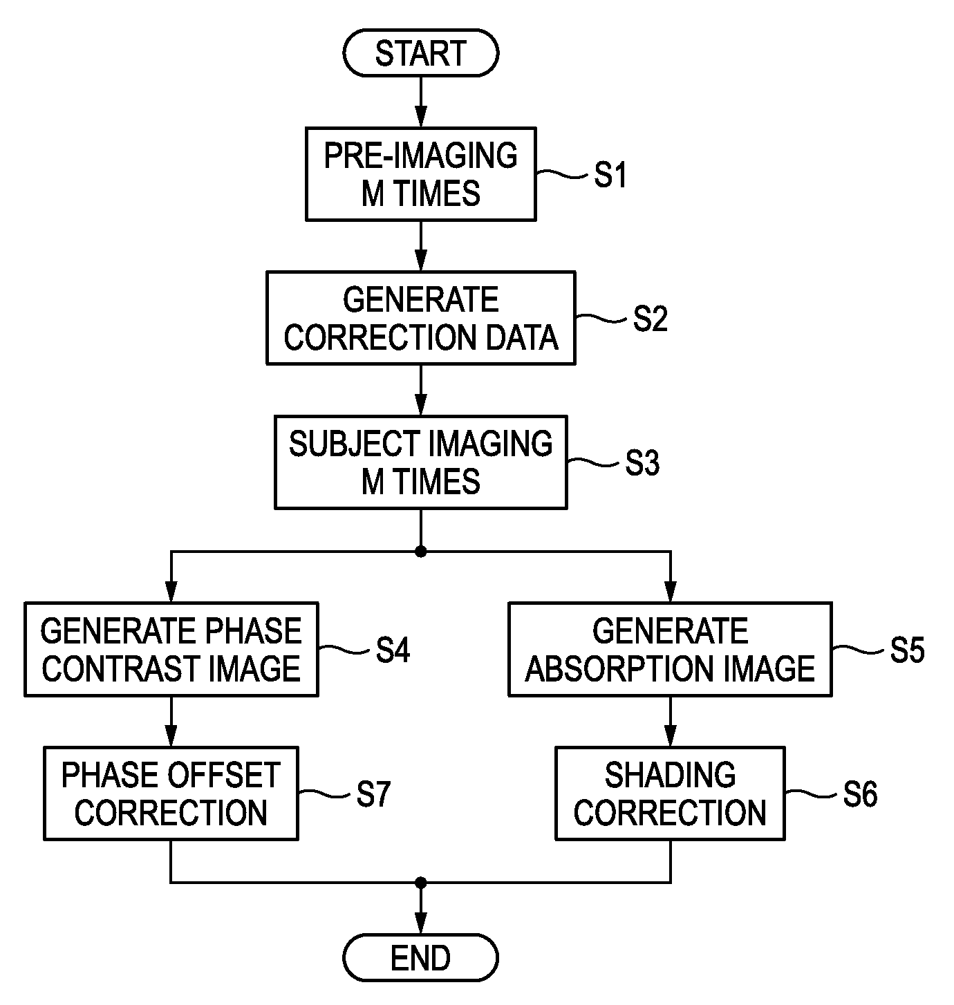
This patent describes a method to create a detailed image of an object using multiple images taken at different optical frequencies. By combining these images, researchers can create an absorption image that highlights important features without obscuring the phase contrast image. This helps to improve the accuracy of diagnosis or inspection by removing any uneven density issues caused by the first grating and the grating pattern. This method also reduces the burden on the subject as separate imaging is not required for the absorption image.

Problems solved by technology

However, the smaller the atomic number of the element configuring material, the X-ray absorption ability is reduced.
Accordingly, for the soft biological tissue or soft material, a difference of the X-ray absorption abilities is small and thus it is not possible to acquire an enough contrast of an image.
Thus, since a difference of the X-ray absorption amounts thereof is small, it is difficult to obtain the contrast of an image.

Method used


Image

  • Radiographic system and radiographic image generating method
  • Radiographic system and radiographic image generating method
  • Radiographic system and radiographic image generating method

Examples


Embodiment Construction

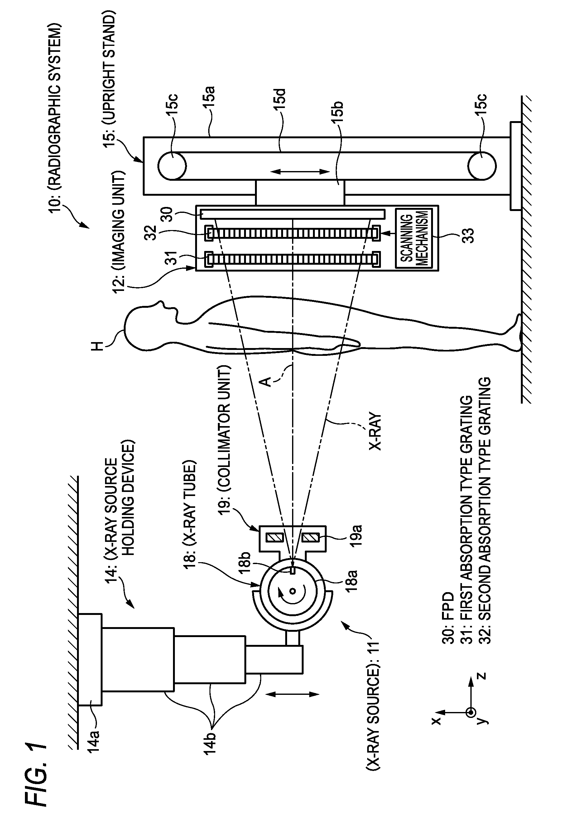
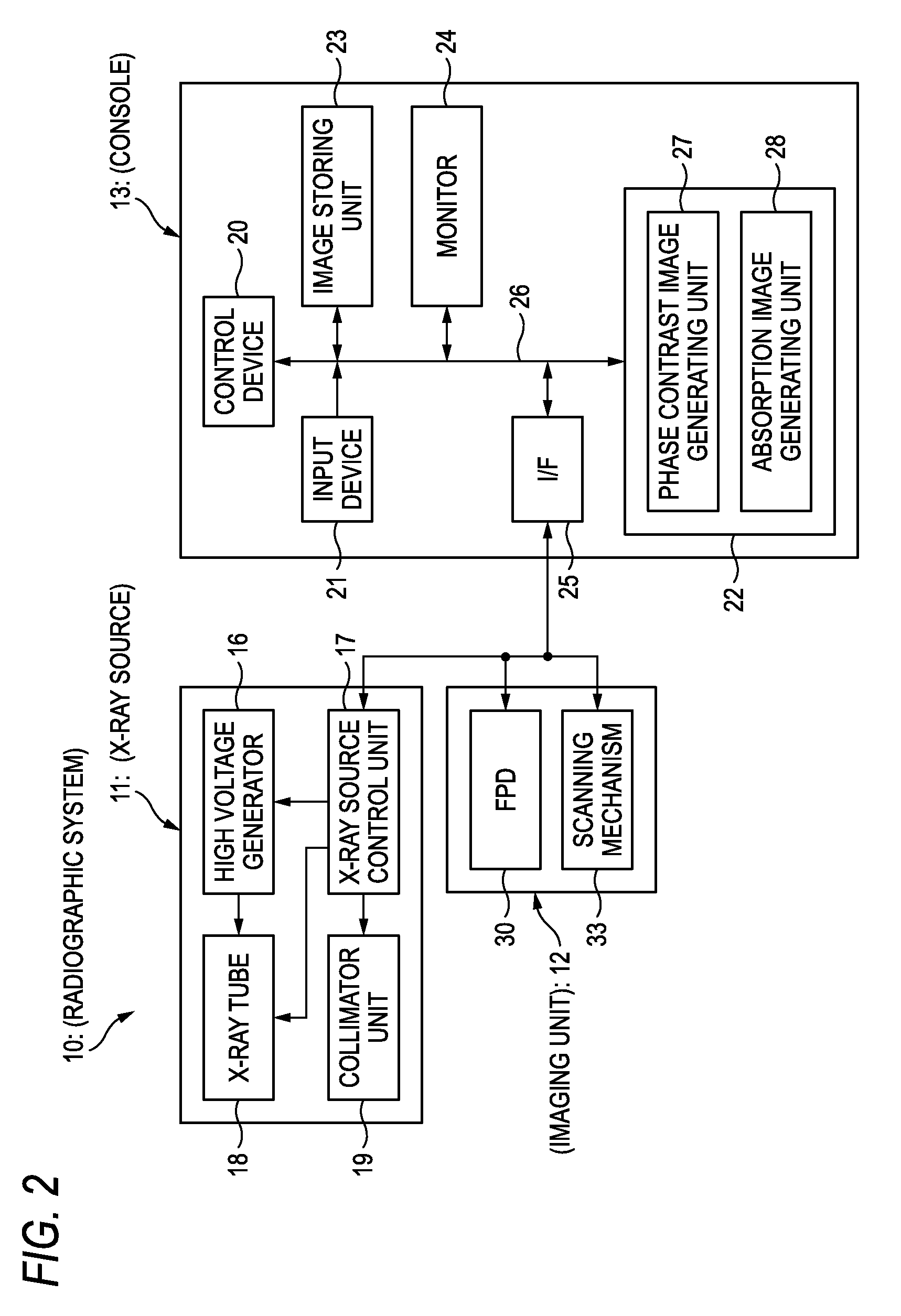
[0033]FIG. 1 schematically illustrates a configuration of an example of radiographic system according to an embodiment of the invention and FIG. 2 illustrates a control block diagram illustrating the radiographic system in FIG. 1.

[0034]An X-ray imaging system 10 is an X-ray diagnosis apparatus that performs an imaging for a subject (patient) H while the patient stands, and includes an X-ray source 11 that X-radiates the subject H, an imaging unit 12 that is opposed to the X-ray source 11, detects the X-ray having penetrated the subject H from the X-ray source 11 and thus generates image data and a console 13 that controls an exposing operation of the X-ray source 11 and an imaging operation of the imaging unit 12 based on an operation of an operator, calculates the image data acquired by the imaging unit 12 and thus generates a phase contrast image and an absorption image.

[0035]The X-ray source 11 is held so that it can be moved in an upper-lower direction (x direction) by an X-ray ...


PUM

PropertyMeasurementUnit
peak wavelengthaaaaaaaaaa
tube voltageaaaaaaaaaa
thickness h1aaaaaaaaaa

Abstract

In a radiographic system and a radiographic image generating method that generate a phase contrast image and an absorption image of an subject, the absorption image in which density irregularity is removed or reduced is generated on the basis of a plurality of pieces of image data obtained for generating the phase contrast image.

Description

CROSS REFERENCE TO RELATED APPLICATION[0001]This is a continuation of International Application No. PCT / JP2011 / 074552 filed on Oct. 25, 2011, and claims priority from Japanese Patent Application No. 2010-241099, filed on Oct. 27, 2010, the entire disclosures of which are incorporated herein by reference.TECHNICAL FIELD[0002]The present invention relates to a radiographic system and a radiographic image generating method.BACKGROUND ART[0003]Since X-ray attenuates depending on an atomic number of an element configuring a material and a density and a thickness of the material, it is used as a probe for seeing through an inside of a subject. An imaging using the X-ray is widely spread in fields of medical diagnosis, nondestructive inspection and the like.[0004]In a conventional X-ray imaging system, a subject is arranged between an X-ray source that irradiates the X-ray and an X-ray image detector that detects an X-ray image, and a transmission image of the subject is captured. In this ...

Claims


Application Information

Patent Timeline
Patent Type & Authority Patents(United States)
IPC IPC(8): G01N23/04A61B6/00
CPCG01N23/04A61B6/502A61B6/4452A61B6/4233A61B6/484A61B6/4464A61B6/4291A61B6/5282G01N23/041
Inventor ISHII, HIROYASU
Owner FUJIFILM CORP
Learn More