Anchor for use with expandable tubular

a technology for expanding tubulars and anchors, which is applied in the direction of drilling casings, drilling pipes, borehole/well accessories, etc., can solve the problems of limited force the hydraulic jack can apply, the casing may become damaged over time, and the production fluid in the zone is significantly damaged

Active Publication Date: 2014-12-02
WEATHERFORD TECH HLDG LLC
View PDF78 Cites 6 Cited by
  • Summary
  • Abstract
  • Description
  • Claims
  • Application Information

AI Technical Summary

Problems solved by technology

The casing may become damaged over time due to corrosion, perforating operations, splitting, collar leaks, thread damage, or other damage.
The damage may be to the extent that the casing no longer isolates the zone on the outside of the damaged portion.
The damaged portion may cause significant damage to production fluid in the zones or inside the casing as downhole operations are performed.
The hydraulic jack is limited in the amount of force it can apply to the expansion cone.
Further, the hydraulic jack requires a high pressure pump to operate which adds to the cost of the operation.
Moreover, the work string must be sealed so pump pressure can be applied to operate the hydraulic jack which makes it difficult to pump fluid down to the expansion cone in order to lubricate the cone during expansion.
Still further, the hydraulic jack has a very small and limited stroke.

Method used


Image

  • Anchor for use with expandable tubular
  • Anchor for use with expandable tubular
  • Anchor for use with expandable tubular

Examples


Embodiment Construction

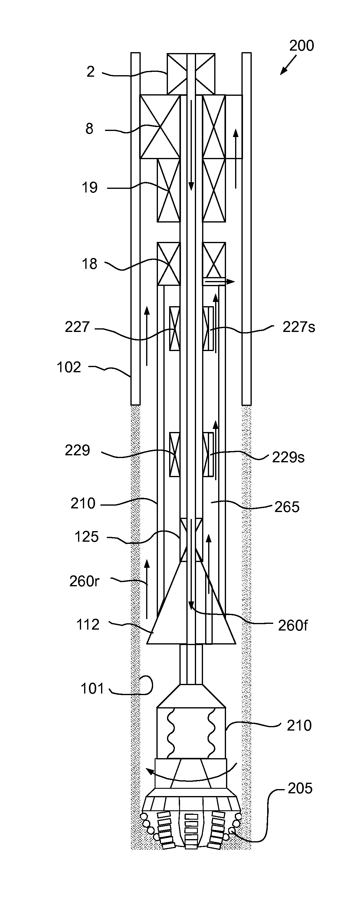
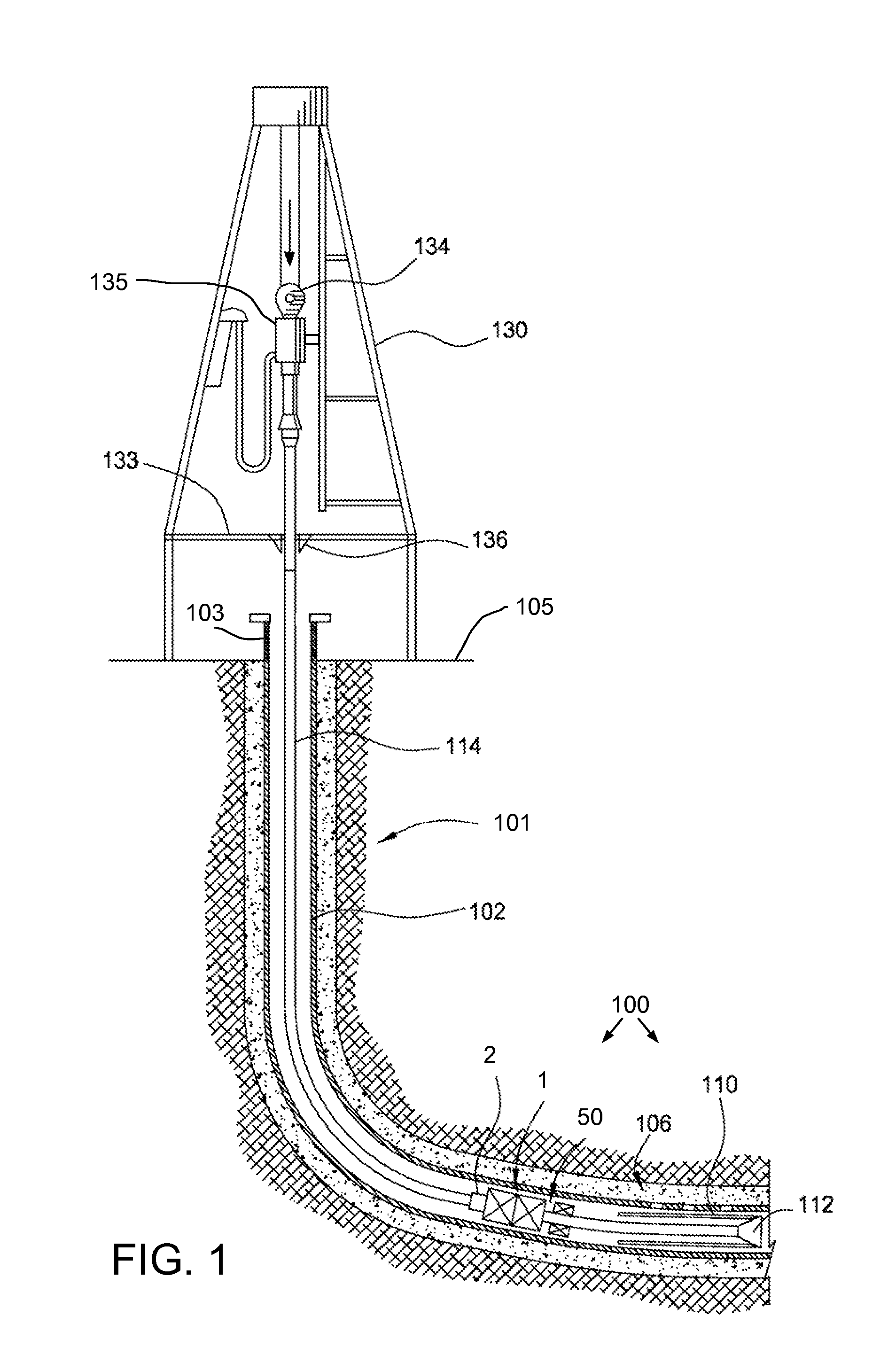
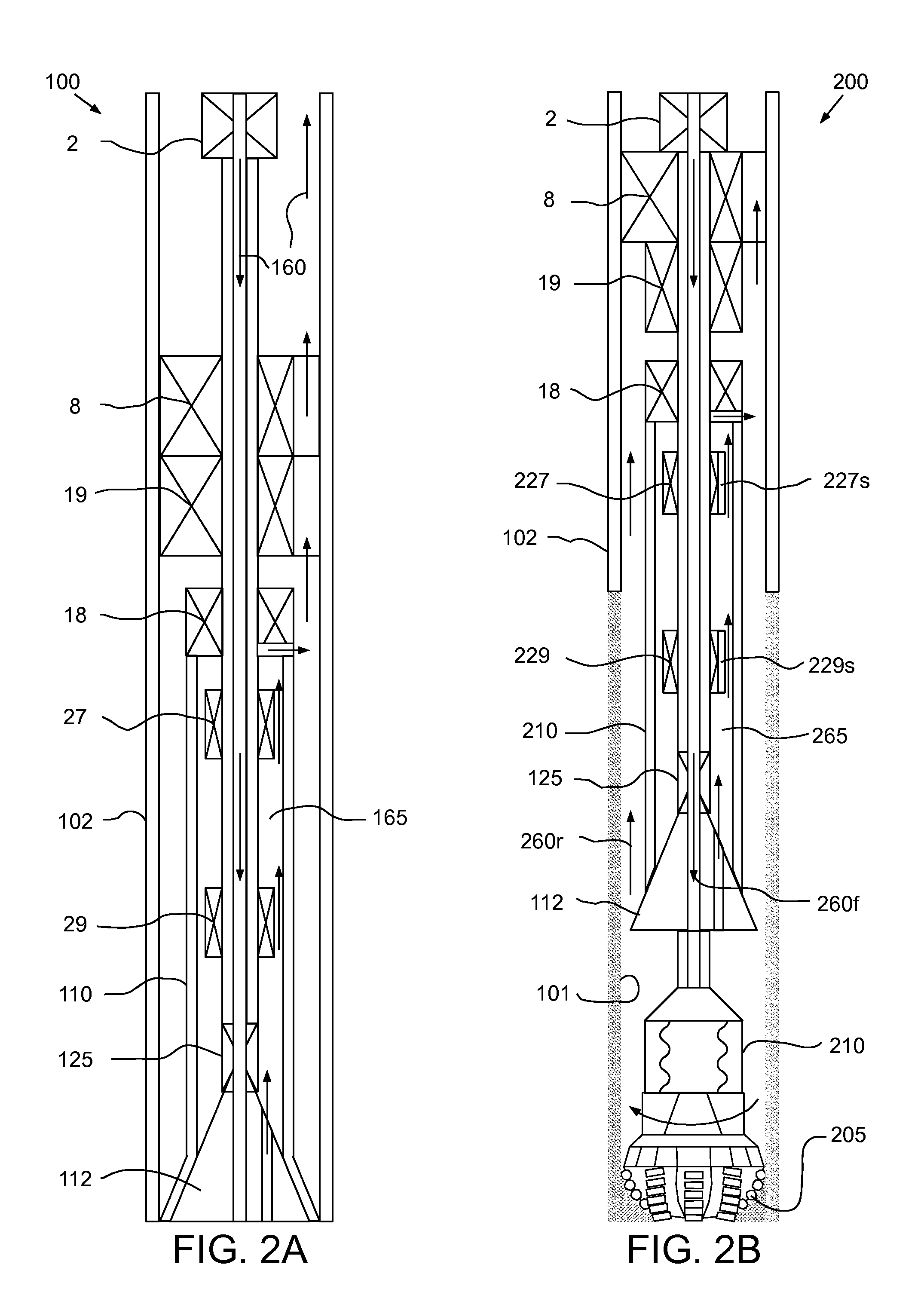
[0021]FIG. 1 illustrates a bottom hole assembly (BHA) 100 deployed to a damaged portion 106 of casing 102, according to one embodiment of the present invention. FIG. 2A illustrates operation of the BHA 100. A wellbore 101 may include the casing 102 cemented into place and extending from a wellhead 103 located at a surface 105 of the earth. The casing 102 may include the damaged portion 106. The BHA 100 may be adapted to repair the damaged portion 106 of the casing 102. The damaged portion 106 of the casing 102 may be caused by a perforation operation; however, it should be appreciated that the damaged portion 106 may be the result of any damage to the casing 102 including, but not limited to, corrosion, thread damage, collar damage, damage caused by cave-in, and / or damage caused by earthquakes. The BHA 100 may include an anchor 1, a setting tool 50 and an expandable tubular, such as a casing patch 110. The setting tool 50 may include a work string and an expander 112. The BHA 100 ma...


PUM


Abstract

A method of lining a wellbore includes deploying a BHA into the wellbore using a conveyance. The BHA includes setting tool, an anchor, and an expandable tubular. The method further includes pressurizing a bore of the setting tool, thereby releasing the anchor from the setting tool. The method further includes pulling the conveyance, thereby: extending the anchor into engagement with a casing of the wellbore, pulling an expander of the setting tool through the expandable tubular, and expanding the tubular into engagement with an open and / or cased portion of the wellbore and retracting the anchor.

Description

CROSS-REFERENCE TO RELATED APPLICATIONS[0001]This application claims benefit of U.S. Prov. Pat. App. No. 61 / 371,082, filed Aug. 5, 2010, which is herein incorporated by reference in its entirety.BACKGROUND OF THE INVENTION[0002]1. Field of the Invention[0003]Embodiments of the present invention generally relate to an anchor for use with an expandable tubular.[0004]2. Description of the Related Art[0005]In the drilling of oil and gas wells, a wellbore is formed using a drill bit disposed at a lower end of a drill string that is urged downwardly into the earth. After drilling to a predetermined depth or when circumstances dictate, the drill string and bit are removed and the wellbore is lined with a string of casing. An annulus is thereby formed between the string of casing and the formation. A cementing operation is then conducted in order to fill the annular area with cement. The combination of cement and casing strengthens the wellbore and facilitates the isolation of certain areas...

Claims


Application Information

Patent Timeline
Patent Type & Authority Patents(United States)
IPC IPC(8): E21B23/04E21B23/01E21B43/10
CPCE21B43/103E21B23/01E21B29/10
Inventor GIROUX, RICHARD LEEKENDZIORA, LARRY A.RING, LEV
Owner WEATHERFORD TECH HLDG LLC
Why Eureka
Try Eureka