Metal seam mount

a seam mount and metal technology, applied in the field of metal seam mounts, can solve the problems of cracking or splitting, damage to the roof or objects below, and difficult installation, and achieve the effect of improving seam gripping

Active Publication Date: 2014-12-02
LIFETIME TOOL & BUILDING PROD
View PDF13 Cites 6 Cited by
  • Summary
  • Abstract
  • Description
  • Claims
  • Application Information

AI Technical Summary

Benefits of technology

The invention provides new shapes of bodies, angular tapped holes, and angularly related planar-sided recesses that improve seam gripping. These bodies have openings that allow for easier gripping of metal roof plates and seams. The inward and downward angles of the holes also make it easier to access and connect with the seams without interfering with the roof's appearance. Overall, this invention provides a better and more efficient way to grip and connect metal roof plates and seams.

Problems solved by technology

When torqued sufficiently for the screws to deform the metal of the seam into the spheroid recesses and thus prevent dislodgment of the snow guard from the seam, the screws acting through the seam and recesses may distort inferior bodies causing them to crack or split.
When the screws are tightened insufficiently, the mounts may slide along or off the seams, causing possible damage to the roof or objects below.
Fasteners historically have been perpendicular to the seam and parallel with the plane of the roof surface or panel and have made for difficult installations due to their close proximity to the panel, leaving little room for either hand or electric impact tools.
Additionally, the sight line of the installer is impeded by the close proximity to the roof panel surface.
As such installer frustration and roof panel damage are common in the trade.

Method used


Image

  • Metal seam mount
  • Metal seam mount
  • Metal seam mount

Examples


Embodiment Construction

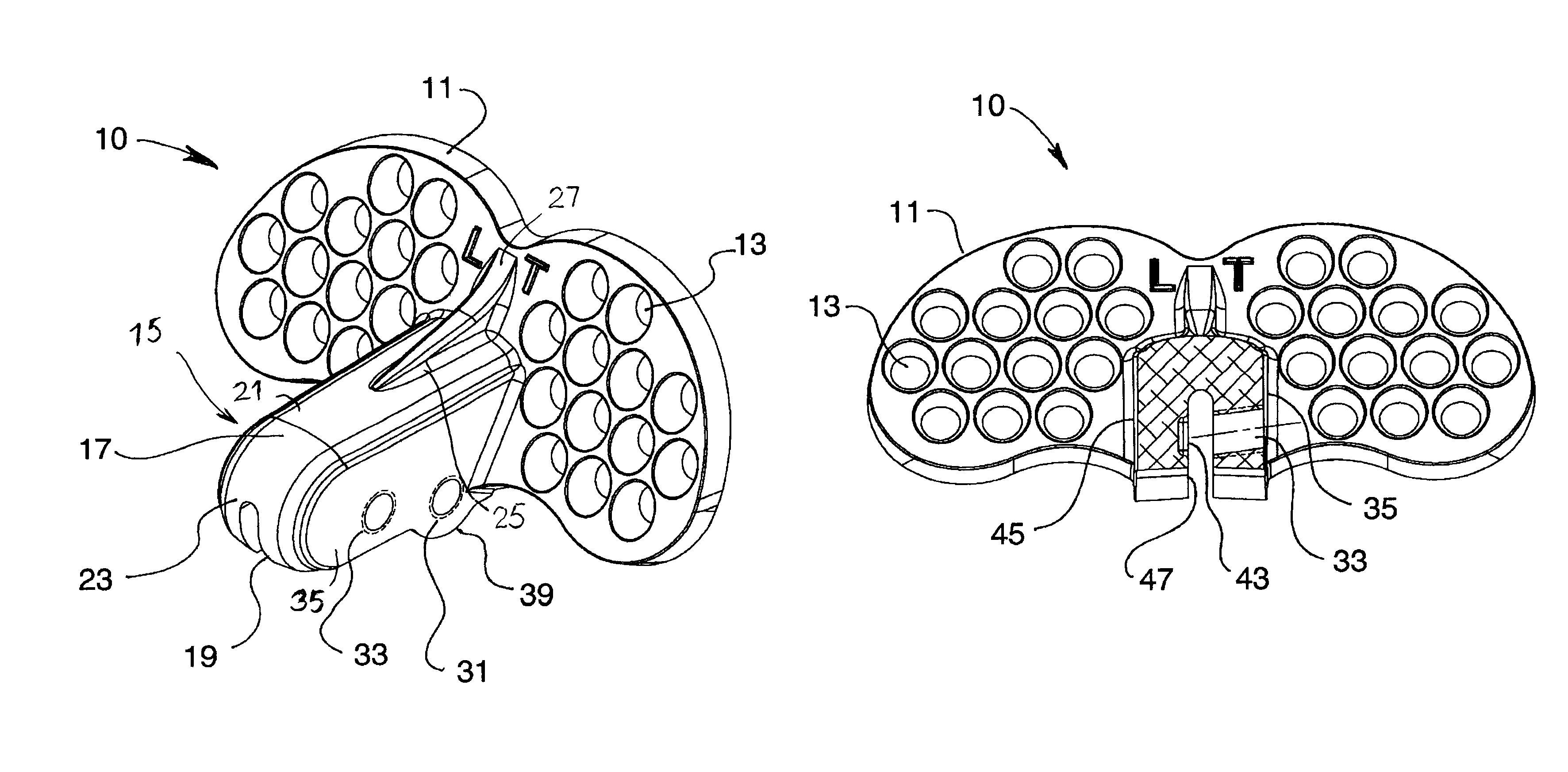
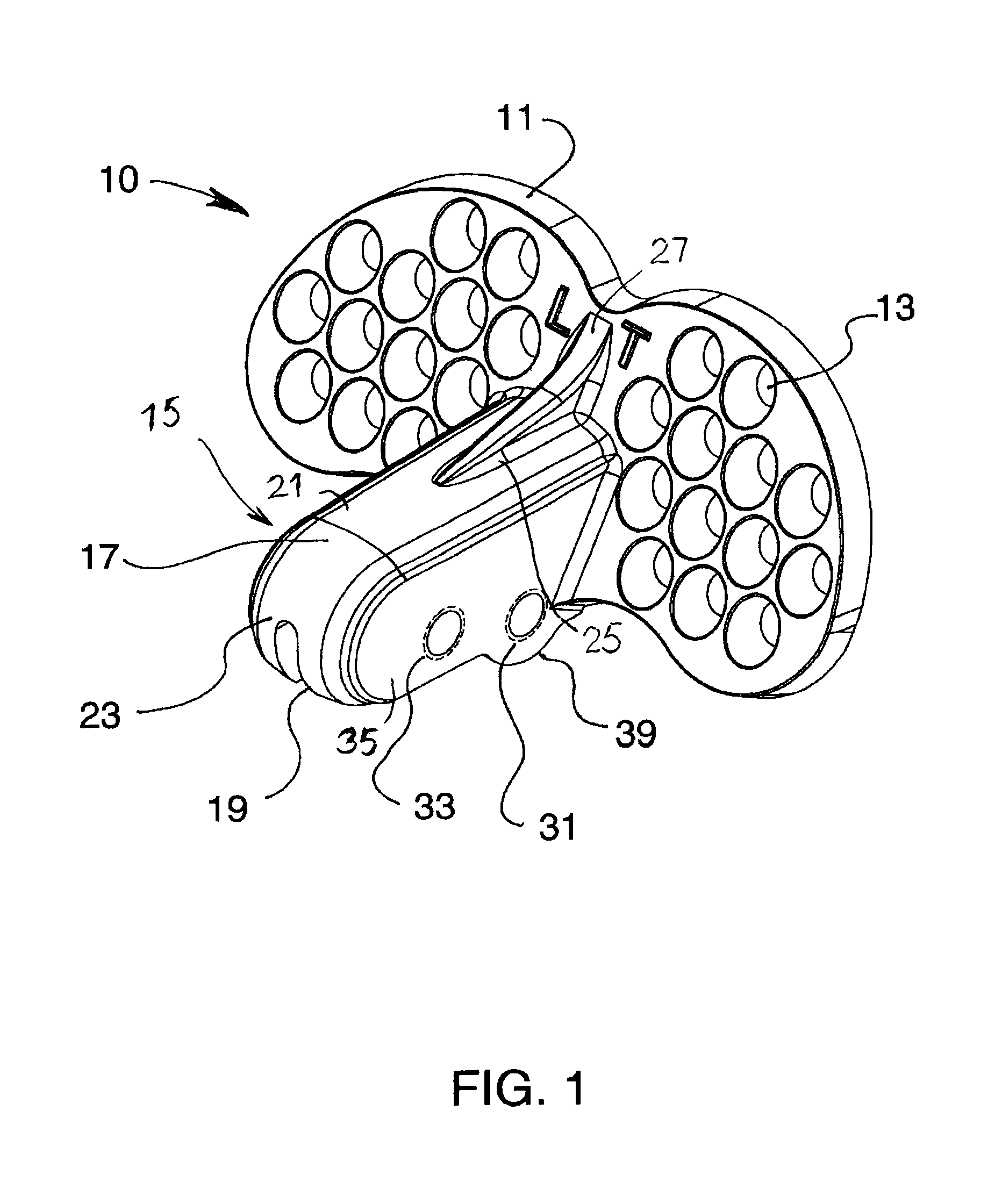
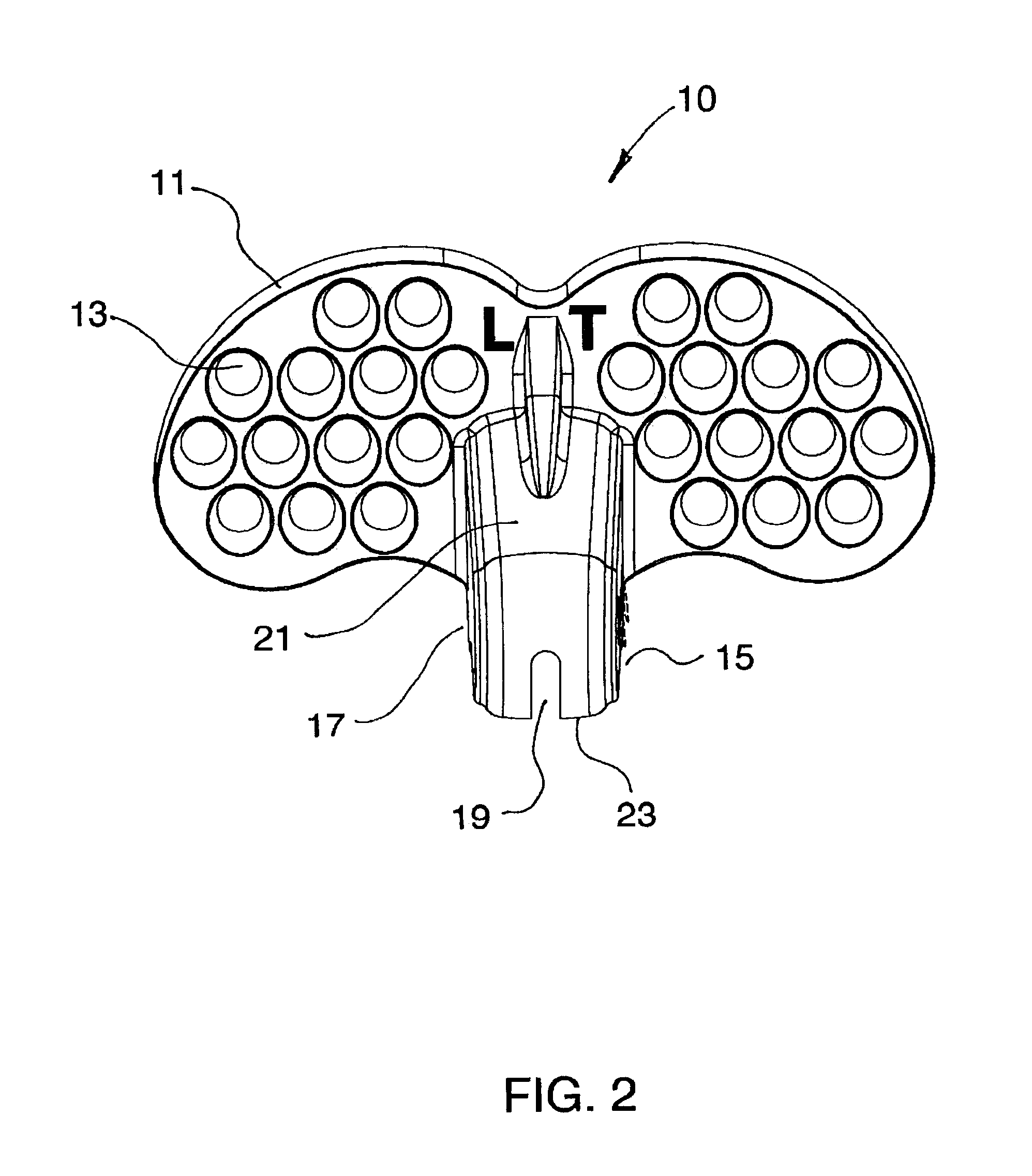
[0034]A snow brake 10 shown in FIGS. 1-13 is an example of a metal plate seam mount. Snow brake 10 has a flat snow blade 11 with holes 13. A seam mounting and clamping portion 15 has a body 17 with an upward groove 19 that extends through the mounting portion body 17 and the flat blade 11. A top 21 and front 23 of the body 17 has a rigidifying gusset 25 which curves 27 onto the front of the blade 11. The snow brake is cast as a single unit.

[0035]Threaded downward angled holes 31, 33 are formed through one side 35 of the body. Complementary rectangular or square recesses 41, 43 are formed in the opposite side's 45 inner face 47. The first and second sides respectively have first and second inner surfaces, and wherein the downward angle of the at least one fastener-receiving threaded hole is about 5° to 20° to a direction perpendicular to the first inner surface. The first and second sides respectively have first and second inner surfaces, and wherein the downward angle of the at leas...


PUM


Abstract

Snow guards and mounts for attaching to seams of metal roofs have tops, spaced sides and inward and downward extending holes for elliptical tipped set screws. Square recesses opposite inner extremities of the holes form square bends in the seams. One screw and recess deform two layers below a rolled seam. Another screw and recess deform five layers in the rolled seam. Bottom lobes near one support provide a lowered hole and a lowered opposite recess. Snow blades extend upward and outward from the top and sides and downward to near a level of the bottoms of the sides.

Description

[0001]This application claims the benefit of U.S. Provisional Application No. 61 / 611,146 filed Mar. 15, 2012, which is hereby incorporated by reference in its entirety as if fully set forth herein.BACKGROUND OF THE INVENTION[0002]Double lock standing seams or double standing seams in metal roofs are formed as rectangular reentrant bends in edges of overlapping metal sheets. The seams stand about one inch or more above the plane of the sheets, and the rectangular reentrant bends occupy about an upper one-half inch of the seams.[0003]Connectors to connect objects, for example snow guards, to the roof have grooved bodies for spanning the seams. Threaded openings in one side of the groove receive screws. The opposite side has spheroid internal recesses for receiving and holding portions of the seams that are pushed into the recesses by the screws. The screws should be tightened sufficiently to distort and hold the seams using powered wrenches or hand operated wrenches. When torqued suff...

Claims


Application Information

Patent Timeline
IPC IPC(8): E04D13/10F16M13/02E04D13/00
CPCF16M13/02E04D13/10
Inventor CLINE, ROGER M.
Owner LIFETIME TOOL & BUILDING PROD
Why Eureka
Try Eureka