
Cavitation device of underwater moving body and underwater moving body having the same

a cavitation device and underwater moving technology, applied in underwater equipment, special-purpose vessels, vessel construction, etc., can solve the problems of sever problems, large change of lift and drag, and underwater moving body sever problems, and achieve the effect of stably moving

Active Publication Date: 2014-11-11
AGENCY FOR DEFENSE DEV
View PDF6 Cites 3 Cited by
  • Summary
  • Abstract
  • Description
  • Claims
  • Application Information

AI Technical Summary

Benefits of technology

The patent describes a cavitation device that can generate a partial cavity and a supercavity on the surface of an underwater moving body. This device includes a plurality of flap-up / down members that are rotatably connected to the body and disposed in a matrix form. A pressing module is used to flapp up the flap-up / down members to create the cavity, which is generated as the flap-up / down members are rotated and inclined from the outer surface of the body. The device can allow the underwater moving body to move stably. The patent also describes an underwater moving body that includes the cavitation device.

Problems solved by technology

Firstly, the conventional cavitation device causes a great change of lift and drag due to a great cavity size and shape change.
Furthermore, sever problems are occurred to the underwater moving body due to tail-slapping and slamming, the slamming occurring when the cavity implodes (collapses) due to disturbances.

Method used


Image

  • Cavitation device of underwater moving body and underwater moving body having the same
  • Cavitation device of underwater moving body and underwater moving body having the same
  • Cavitation device of underwater moving body and underwater moving body having the same

Examples


Embodiment Construction

[0025]Hereinafter, a cavitation device and an underwater moving body having the same according to the present invention will now be given in detail of the exemplary embodiments, with reference to the accompanying drawings. The same or similar components of one embodiment as or to those of another embodiment will be provided with the same or similar reference numerals, and their detailed explanations will be omitted. A singular expression includes a plural concept unless there is a contextually distinctive difference therebetween.

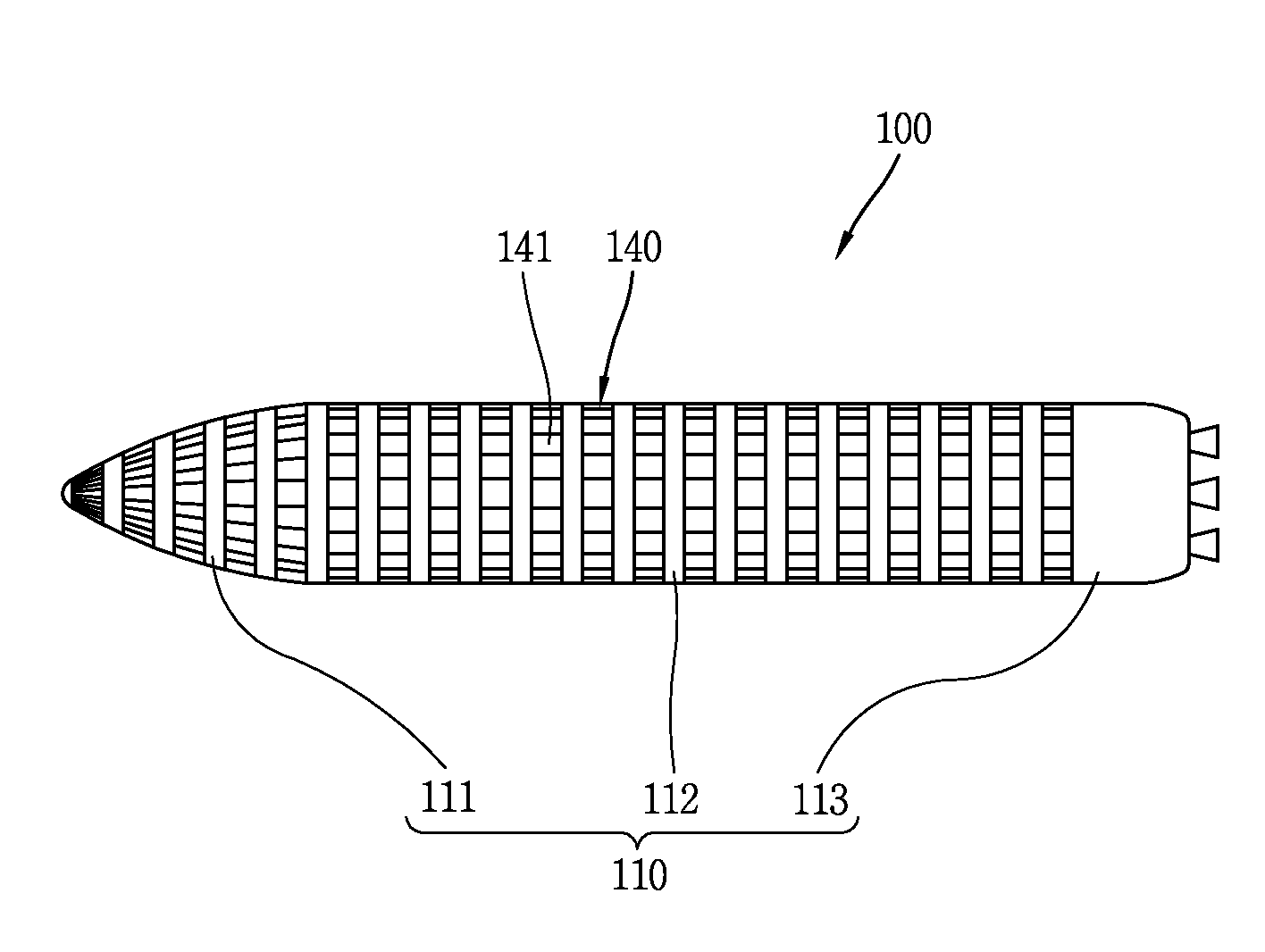
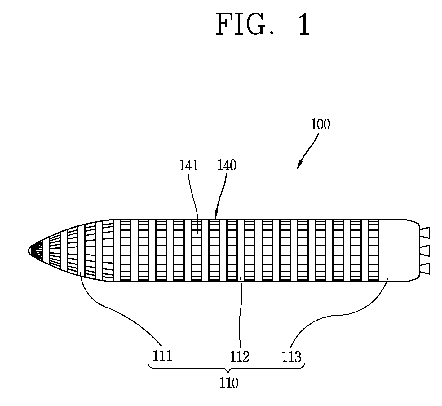
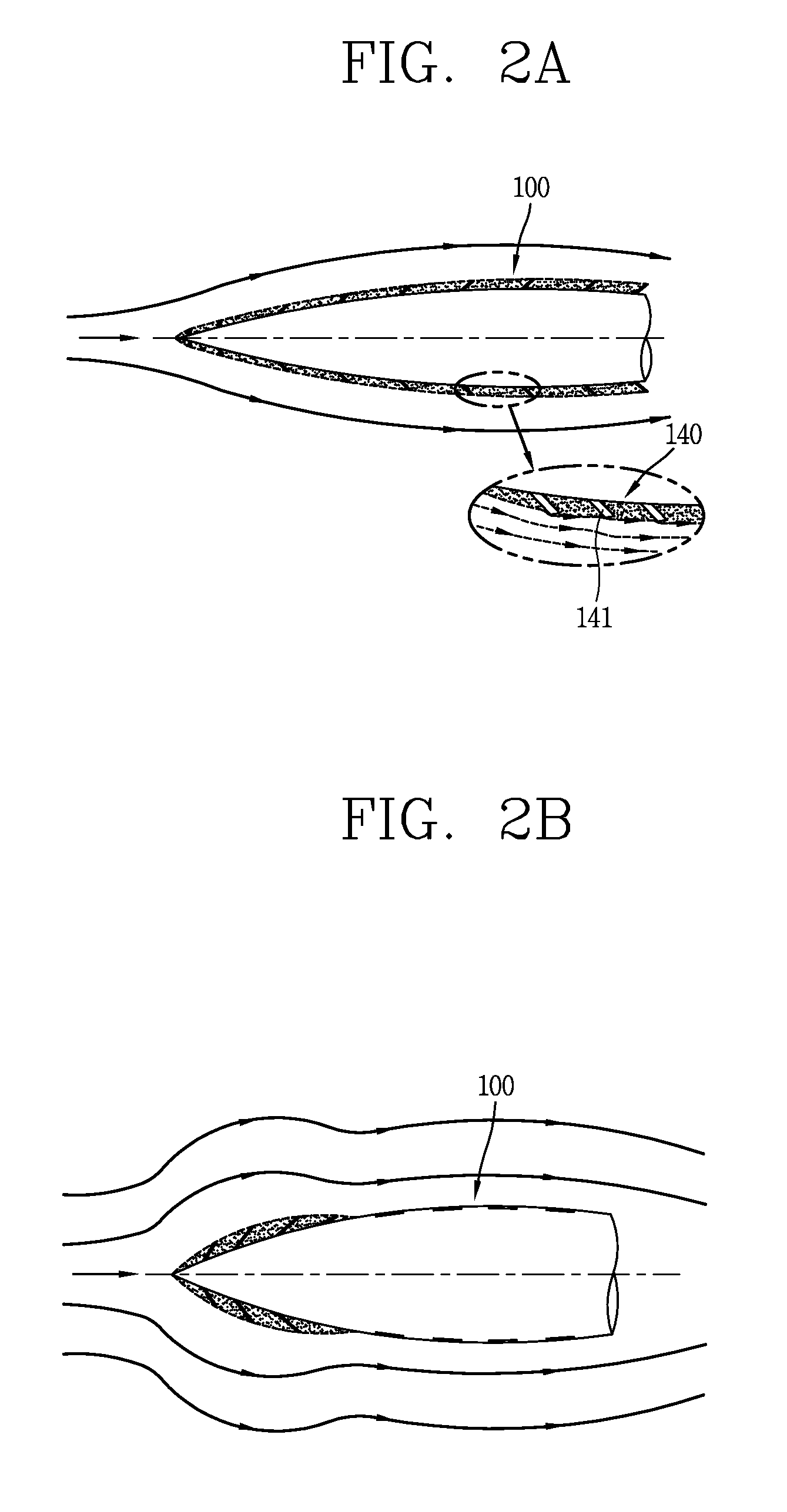
[0026]FIG. 1 is a conceptual view illustrating an underwater moving body according to an embodiment of the present invention, and FIGS. 2A to 2D are conceptual views illustrating generation of a partial cavity and a super cavity.

[0027]FIG. 1 illustrates a super cavity torpedo which moves underwater, as an example of an underwater moving body 100. As shown, the underwater moving body 100 is movable underwater, and has a cylindrical shape between the front sid...


PUM


Abstract

Disclosed are a cavitation device and an underwater moving body having the same. The underwater moving body includes a body; and a cavitation device for generating a cavity which encloses an outer circumferential surface of the body, wherein the cavitation device includes: a plurality of flap-up / down members rotatably connected to the body, disposed to cover the outer circumferential surface, and disposed in a circumferential direction and a lengthwise direction of the body in a matrix form; and a pressing module for flapping up the flap-up / down members such that the cavity is generated, as the flap-up / down members being rotated are inclined from the outer circumferential surface. Under this configuration, the cavitation device can freely generate a partial cavity or a super cavity on the surface of the underwater moving body. Furthermore, a ventilation module for forming a ventilated cavity may be coupled to the cavitation device.

Description

CROSS-REFERENCE TO RELATED APPLICATION[0001]Pursuant to 35 U.S.C. §119(a), this application claims the benefit of earlier filing date and right of priority to Korean Application No. 10-2012-0049179, filed on May 9, 2012, and which is herein expressly incorporated by reference in their entireties.BACKGROUND OF THE INVENTION[0002]1. Field of the Invention[0003]The present disclosure relates to a cavitation device for forming a cavity on the surface of an underwater moving body for very high speed, and an underwater moving body having the same.[0004]2. Background of the Invention[0005]Examples of an underwater moving body include a cylindrical moving body which moves underwater, such as a torpedo and a self-propelled decoy. Such underwater moving body has large friction resistance due to friction by water viscosity. Since the friction resistance occupies most of the entire resistance of the underwater moving body, research to reduce the friction resistance is actively ongoing.[0006]Suc...

Claims


Application Information

Patent Timeline
Patent Type & Authority Patents(United States)
IPC IPC(8): B63B1/36
CPCF42B10/42F42B19/00B63B1/36B63B2001/382Y02T70/10F41F3/08F42B15/22F42B17/00
Inventor JUNG, CHUL MINKIM, CHAN KIPARK, WARN GYU
Owner AGENCY FOR DEFENSE DEV
Learn More