
System and method for flash bypass

a technology of flash bypass and system, applied in the field of solar panels, can solve the problems of affecting panel testing, affecting panel testing, and not supporting such tests in the existing jbox design, and achieve the effect of facilitating correct stand-alone panel testing and facilitating testing

Active Publication Date: 2014-09-23
NEWLIGHT CAPITAL LLC
View PDF42 Cites 117 Cited by
  • Summary
  • Abstract
  • Description
  • Claims
  • Application Information

AI Technical Summary

Benefits of technology

Enables efficient flash testing of solar panels without impacting their output, allowing for accurate stand-alone panel testing and supporting the full assembly of panels with smart Jboxes, while ensuring the bypass device activates correctly during the brief light flash indicative of a test scenario.

Problems solved by technology

However, existing Jbox design does not support such tests.
Mounting smart Jbox electronics that are fed from the panel affects panel testing and does not permit correct stand-alone panel testing.

Method used


Image

  • System and method for flash bypass
  • System and method for flash bypass
  • System and method for flash bypass

Examples


Embodiment Construction

[0024]The following description and drawings are illustrative and are not to be construed as limiting. Numerous specific details are described to provide a thorough understanding. However, in certain instances, well known or conventional details are not described in order to avoid obscuring the description. References to one or an embodiment in the present disclosure are not necessarily references to the same embodiment; and, such references mean at least one.

[0025]The present disclosure includes a system and method to keep the bypass-FET on during a solar panel test. In one exemplary embodiment, an electronic bypass may be used for such a purpose, using solid-state electronic devices. In another exemplary embodiment, a mechanical relay, or even a switch that may be triggered on / off for factory testing in accordance with this disclosure.

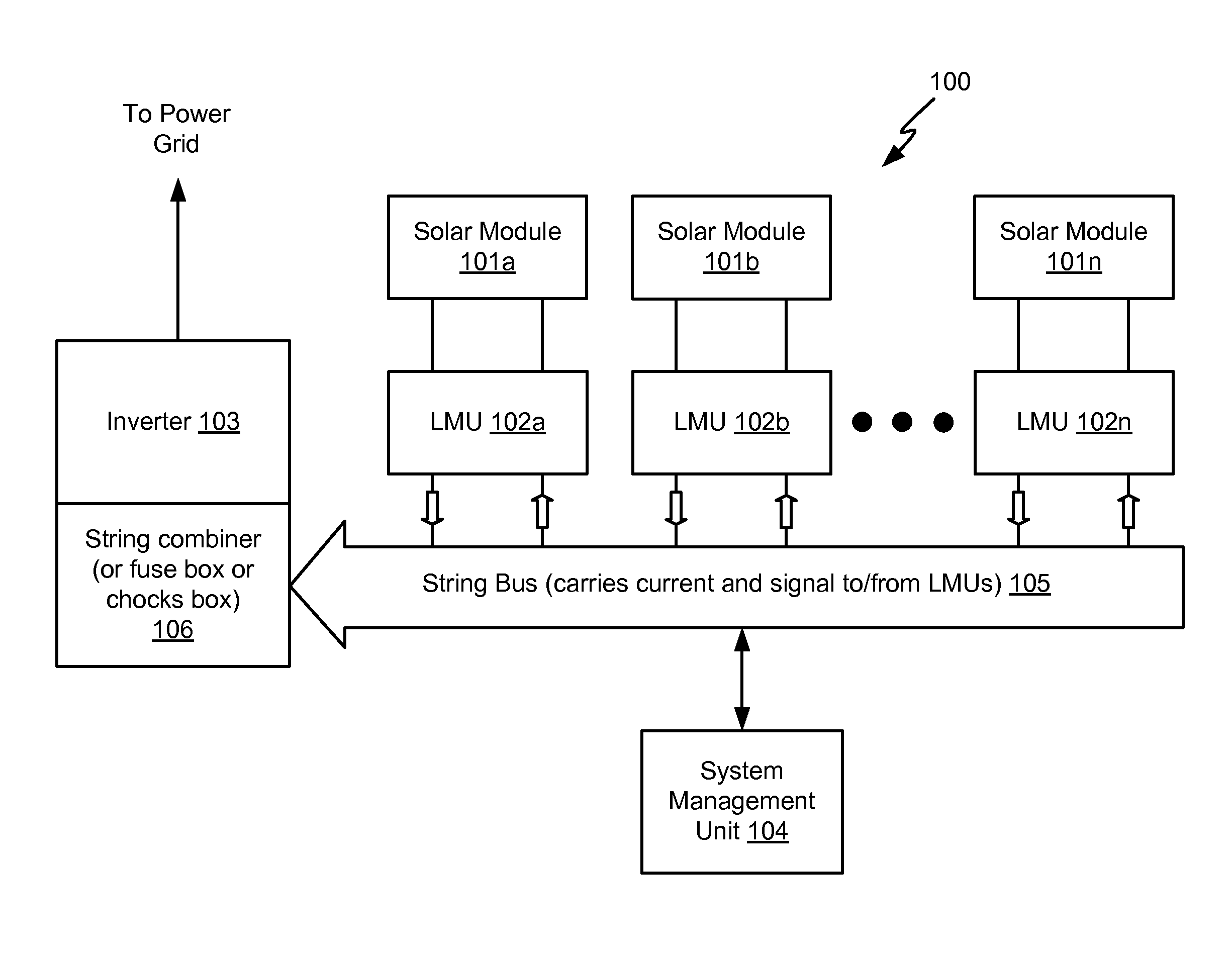
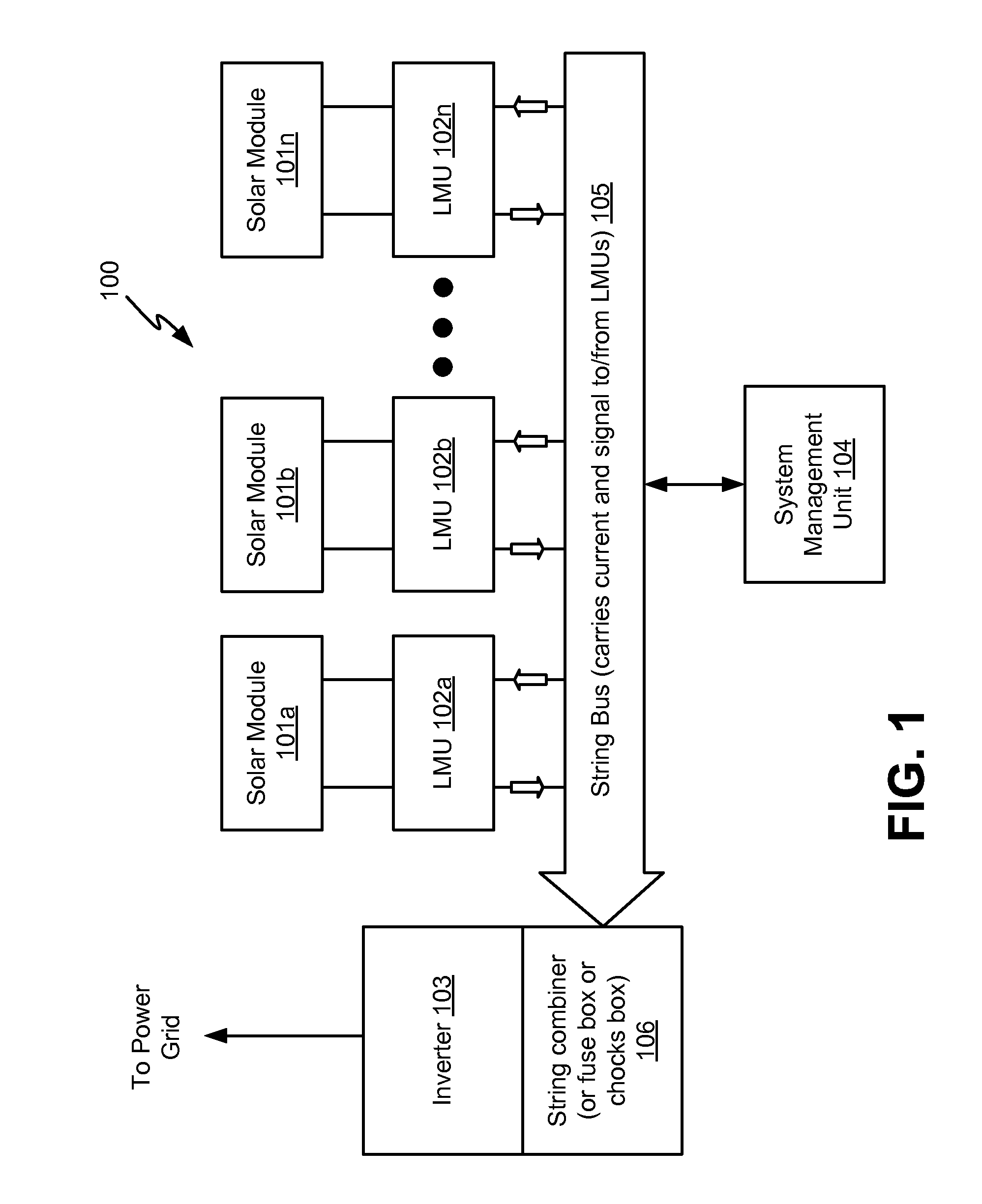
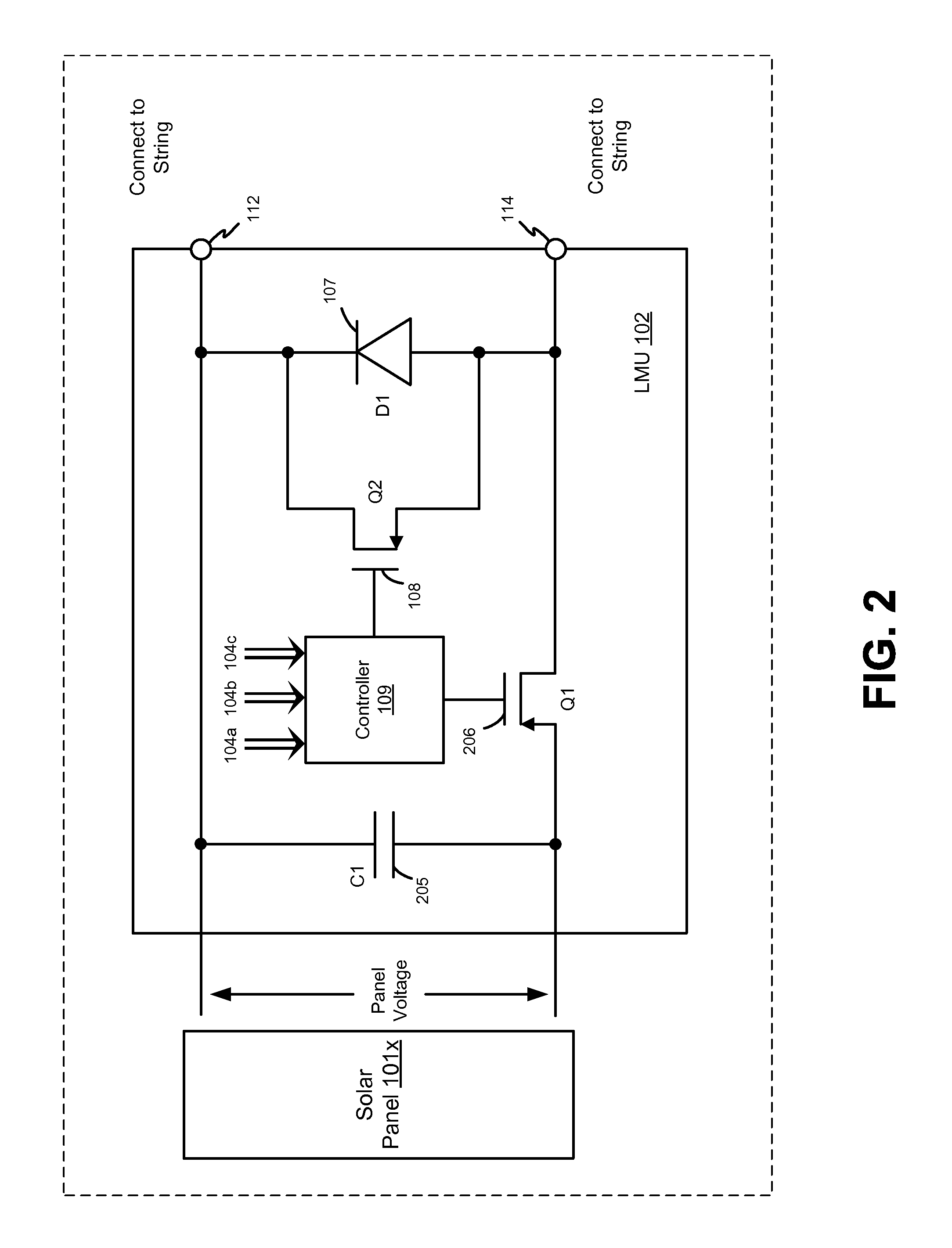
[0026]Referring now to the drawing, FIG. 1 illustrates an exemplary photovoltaic system 100, according to one aspect of the system and method disclo...


PUM


Abstract

A solar photovoltaic panel is disclosed that includes a photovoltaic cell, a local management unit connected between the cell and a string bus, and a bypass device connected to the cell that is operable to bypass the local management unit when conducting a flash test. The panel preferably further includes a transient detector connected to the cell that is operable to sense an output from the cell having a predetermined transient rise time. The transient detector and the bypass device may be contained within a junction box integrated into the panel and may include the local management unit within the junction box. The transient detector may include a switch connected to a circuit that electrically bypasses the local management unit when the switch is turned on as a result of an output transient rise time less than the predetermined time, thus facilitating a flash test of the photovoltaic panel.

Description

CROSS REFERENCE TO RELATED APPLICATIONS[0001]This application claims the benefit of priority of U.S. Provisional Patent Application Ser. No. 61 / 447,622 filed Feb. 28, 2011, which is incorporated herein by reference in its entirety.FIELD OF THE TECHNOLOGY[0002]This disclosure relates generally to solar panels and more particularly to test methods and systems for solar panels during manufacture.BACKGROUND[0003]During manufacturing, solar panel manufacturers need to test the performance of solar panels equipped with an intelligent junction box (Jbox). It is desirable to do this by executing a flash test (subjecting the panels to a flash of light), which test time lasts from a few milliseconds up to 100 milliseconds. Such a flash as is required for this particular testing would not affect the output of the entire device (panel plus Jbox). However, existing Jbox design does not support such tests.[0004]The Jbox has within it a Local Management Unit (LMU). This LMU is typically initially ...

Claims


Application Information

Patent Timeline
Patent Type & Authority Patents(United States)
IPC IPC(8): G01R31/26H01L31/048
CPCG01R31/2605H01L31/0485Y02E10/50H02S40/34Y10T307/773H02S50/10
Inventor AVRUTSKY, MORDECHAY
Owner NEWLIGHT CAPITAL LLC
Learn More