Developing device

a technology of developing device and focusing device, which is applied in the direction of instruments, electrographic process equipment, optics, etc., can solve the problems of image quality decline, and achieve the effect of smooth carrying

Active Publication Date: 2014-09-16
HEWLETT PACKARD DEV CO LP
View PDF5 Cites 4 Cited by
  • Summary
  • Abstract
  • Description
  • Claims
  • Application Information

AI Technical Summary

Benefits of technology

[0008]The present disclosure is to smoothly carry a developer between a stirring and carrying unit and a supplying and carrying unit, thus decreasing the amount of the developer staying in the stirring and carrying unit and allowing the developer to be easily, sufficiently mixed and stirred.
[0011]According to the structure of the developing device, the developer in the stirring and carrying unit is carried to the position of the second and third spiral wings while being stirred by the first spiral wing. Thus, since the second and third spiral wings are opposite in spiral direction, are equal in number of spiral lines (e.g., double spiral form) and lead, and are equal in position of adjacent ends in a rotational direction, the developer is collected toward a center portion between the second and third spiral wings and is then subject to an upward lifting action. In addition, since the second and third spiral wings are formed in a double spiral, the developer is subject to the lifting action several times for one revolution such that the developer is efficiently carried to the supplying and carrying unit via the communication portion. Thus, since the developer is smoothly carried between the stirring and supplying unit and the supplying and carrying unit, stay of the developer in the stirring and carrying unit may be decreased to thus easily obtain a stable flow of the developer. Therefore, a length necessary for a stirring region of the developer may be secured, mixing and stirring performances may be enhanced, and / or the length of the developing device may be easily shortened.
[0013]According the to the structure of the second and third spiral wings, a clearance between ends of the second and third spiral wings and the housing is suppressed to be narrowed, and at the same time a distance between the ends of the second and third spiral wings and the supplying and carrying unit is also suppressed to be shortened. Thus, carrying loss is decreased, and lifting force acting on the developer is kept in a high state, thereby easily enhancing the carrying efficiency.
[0015]According to the carrying rate, flow balance of the developer circulating the stirring and carrying unit and the supplying and carrying unit according to the carriability of the developer by the stirring and carrying unit and the supplying and carrying unit, the amount of the developer supplied to the developer bearing member from the supplying and carrying unit may be easily, properly maintained.
[0017]According to the structure of the supplying and carrying unit, a larger space for receiving the developer pushed and lifted by the second and third spiral wings of the stirring and carrying unit is secured in the supplying and carrying unit, and thus the developer may be smoothly carried.

Problems solved by technology

For example, in case the supplying and carrying unit is disposed above the stirring and carrying unit, the amount of the developer lifted by a carrying pressure or a magnetic force is not sufficiently secured, so that a large amount of developer may stay within the stirring and carrying unit.
Therefore, a sufficient mixing, stirring and the like of the developer may be hindered, thus resulting in a decline in image quality.

Method used


Image

  • Developing device
  • Developing device
  • Developing device

Examples


Embodiment Construction

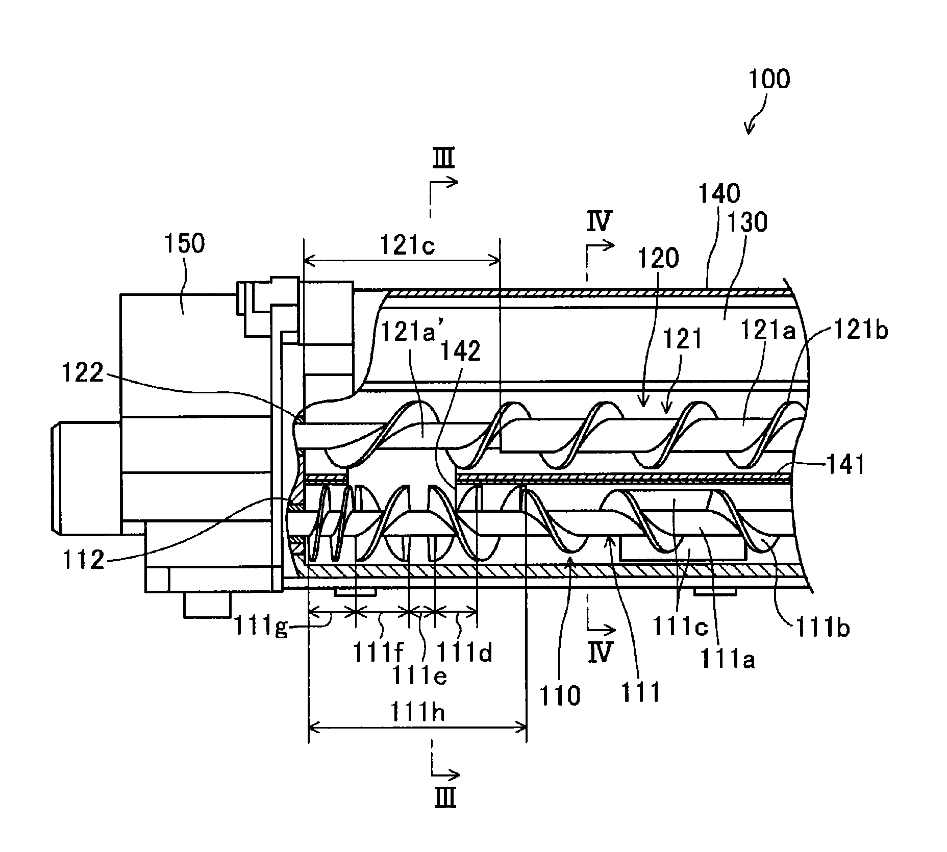
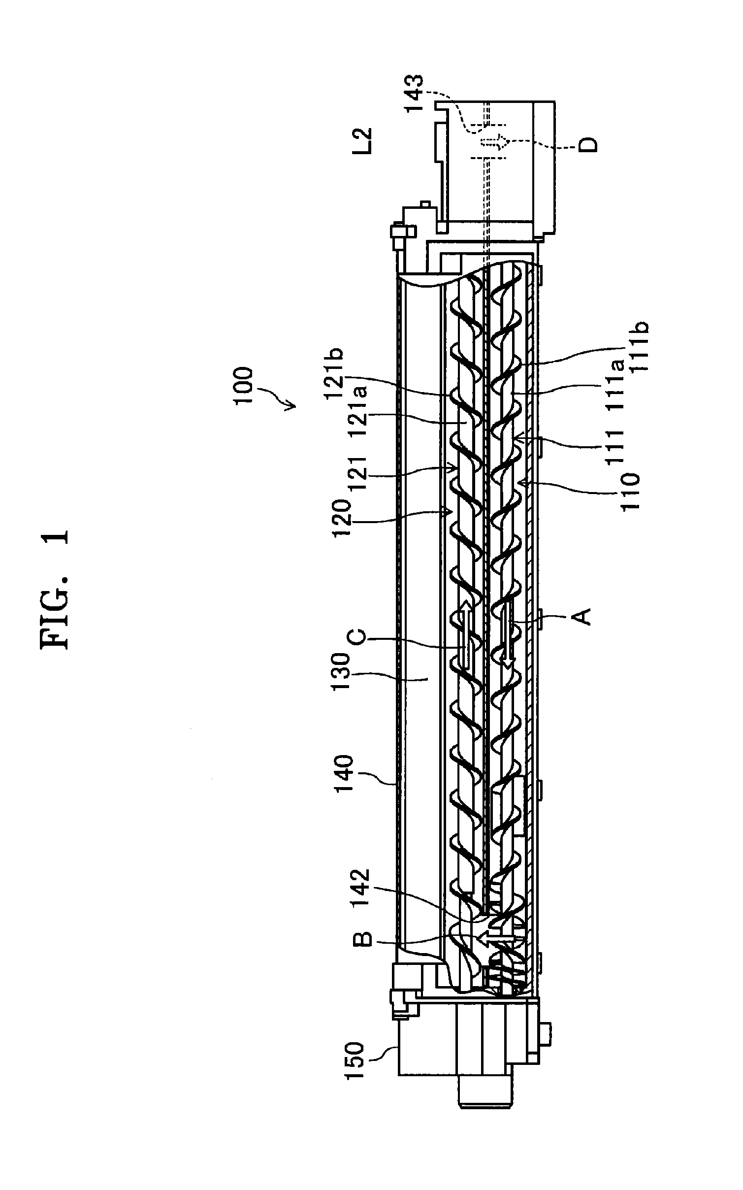
[0023]The present disclosure will now be described more fully with reference to the accompanying drawings, in which exemplary embodiments of the present disclosure are shown. A developing device is installed in an image forming apparatus, for example, as a developing unit, and forms a toner image by developing an electrostatic latent image formed by an exposure of a photosensitive drum to light with a two-component developer containing a toner and a carrier. The formed toner image is transferred on a recording medium, for example, via a transfer belt, heated and fused. Hereinafter, the developing device will be described in more detail.

(Schematic Configuration of Developing Device 100)

[0024]As shown in FIGS. 1 to 4, a developing device 100 is provided with a stirring and carrying unit 110, a supplying and carrying unit 120, and a developing roller (developer bearing member) 130. The stirring and carrying unit 110 is, for example, configured to stir a developer while carrying the dev...


PUM


Abstract

A developing device includes spiral wings, a forward double spiral wing, clearance portion, backward double spiral wing, and short lead backward spiral wing installed on the rotational shaft of a stirring and carrying unit. The forward and backward double spiral wings have spiral directions opposite to each other, and together are formed to have an equal lead to the spiral wings. The supplying and carrying unit is disposed above the stirring and carrying unit, and the supplying and carrying unit and the stirring and carrying unit are divided by a partition having a communication portion installed at a position corresponding to the forward and backward double spiral wings.

Description

CROSS-REFERENCE TO RELATED APPLICATIONS[0001]This application claims the benefit of Japanese Patent Application No. 2011-268281, filed on Dec. 7, 2011, in the Japanese Patent Office, and Korean Patent Application No. 10-2012-0136555, filed on Nov. 28, 2012, in the Korean Intellectual Property Office, the disclosures of which are incorporated herein in their entirety by reference.BACKGROUND[0002]1. Field[0003]The present disclosure relates to a developing device used in an image forming apparatus using an electrophotographic method.[0004]2. Description of the Related Art[0005]An electrophotographic image forming apparatus, which is employed in a digital copier or printer, forms an electrostatic latent image by exposing to light a surface of a photosensitive drum which is uniformly charged, forms a visualized toner image by developing the electrostatic latent image with a toner, and records an image by transferring the toner image on a recording medium. In such an image forming appara...

Claims


Application Information

Patent Timeline
Patent Type & Authority Patents(United States)
IPC IPC(8): G03G15/08
CPCG03G15/087G03G15/0893G03G2215/083G03G2215/0833
Inventor IWATA, NAOYA
Owner HEWLETT PACKARD DEV CO LP
Why Eureka
Try Eureka