
Spindle motor and hard disk drive including the same

Inactive Publication Date: 2014-09-16
SAMSUNG ELECTRO MECHANICS CO LTD
View PDF10 Cites 2 Cited by
  • Summary
  • Abstract
  • Description
  • Claims
  • Application Information

AI Technical Summary

Benefits of technology

This patent describes a new spindle motor design that has several technical benefits. First, it is stronger and provides space for lubricating fluid, making it more reliable. Second, it reduces the number of components needed, saving manufacturing costs. Lastly, it increases the rigidity of the bearing, allowing for longer spindle motor life while staying thin and compact.

Problems solved by technology

In addition, the lubricating fluid injected into the hydrodynamic bearing assembly may be leaked to the outside due to an external impact or the amount thereof may be reduced due to evaporation.
Due to the above-mentioned phenomena, the hydrodynamic bearing may not be able to generate sufficient fluid dynamic pressure, which may lead problems in terms of the performance and lifespan of a spindle motor.
Further, when an external impact is transferred to a spindle motor from the outside during the driving thereof, internal components in the spindle motor may be deformed, having an adverse affect on the driving of the spindle motor.

Method used


Image

  • Spindle motor and hard disk drive including the same
  • Spindle motor and hard disk drive including the same
  • Spindle motor and hard disk drive including the same

Examples


first embodiment

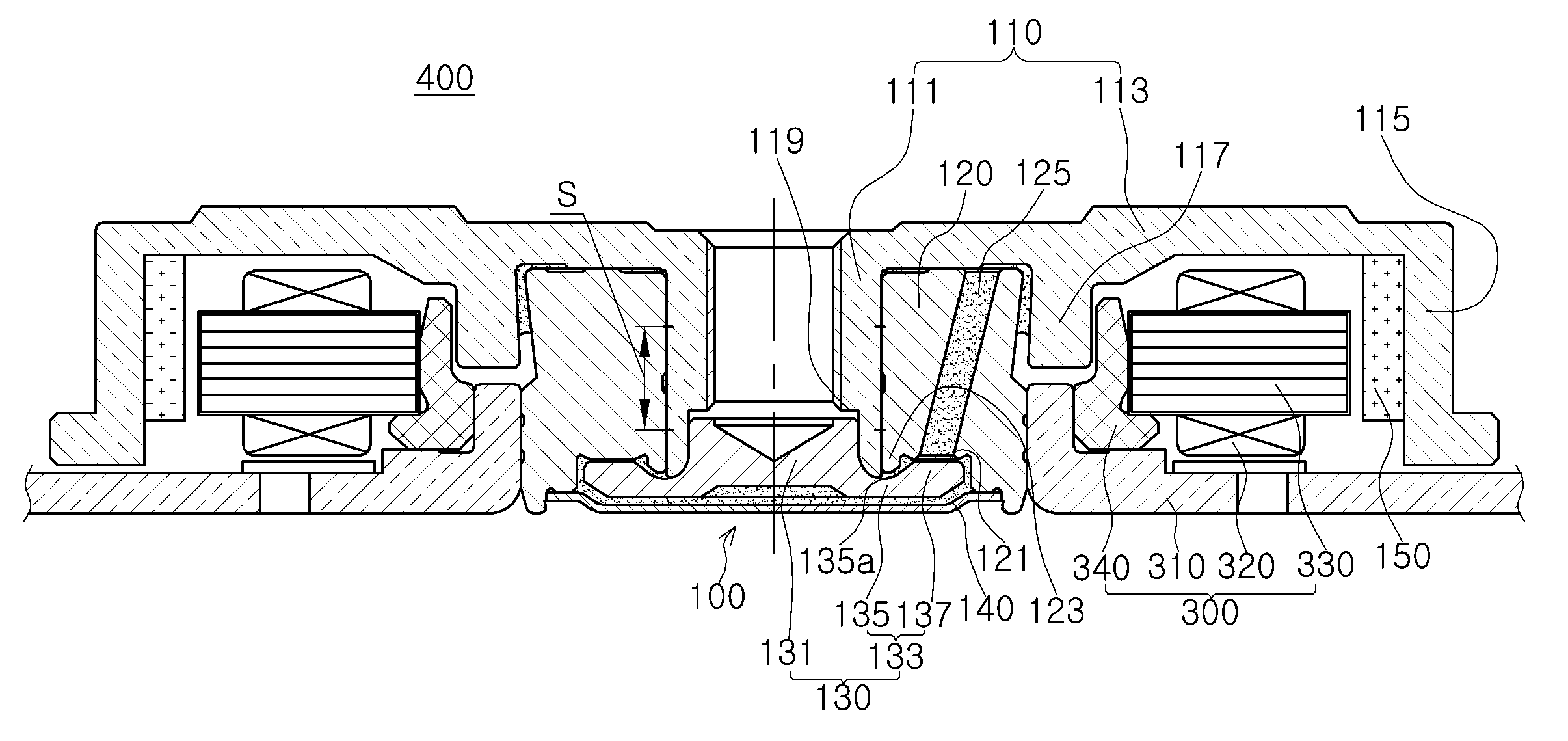
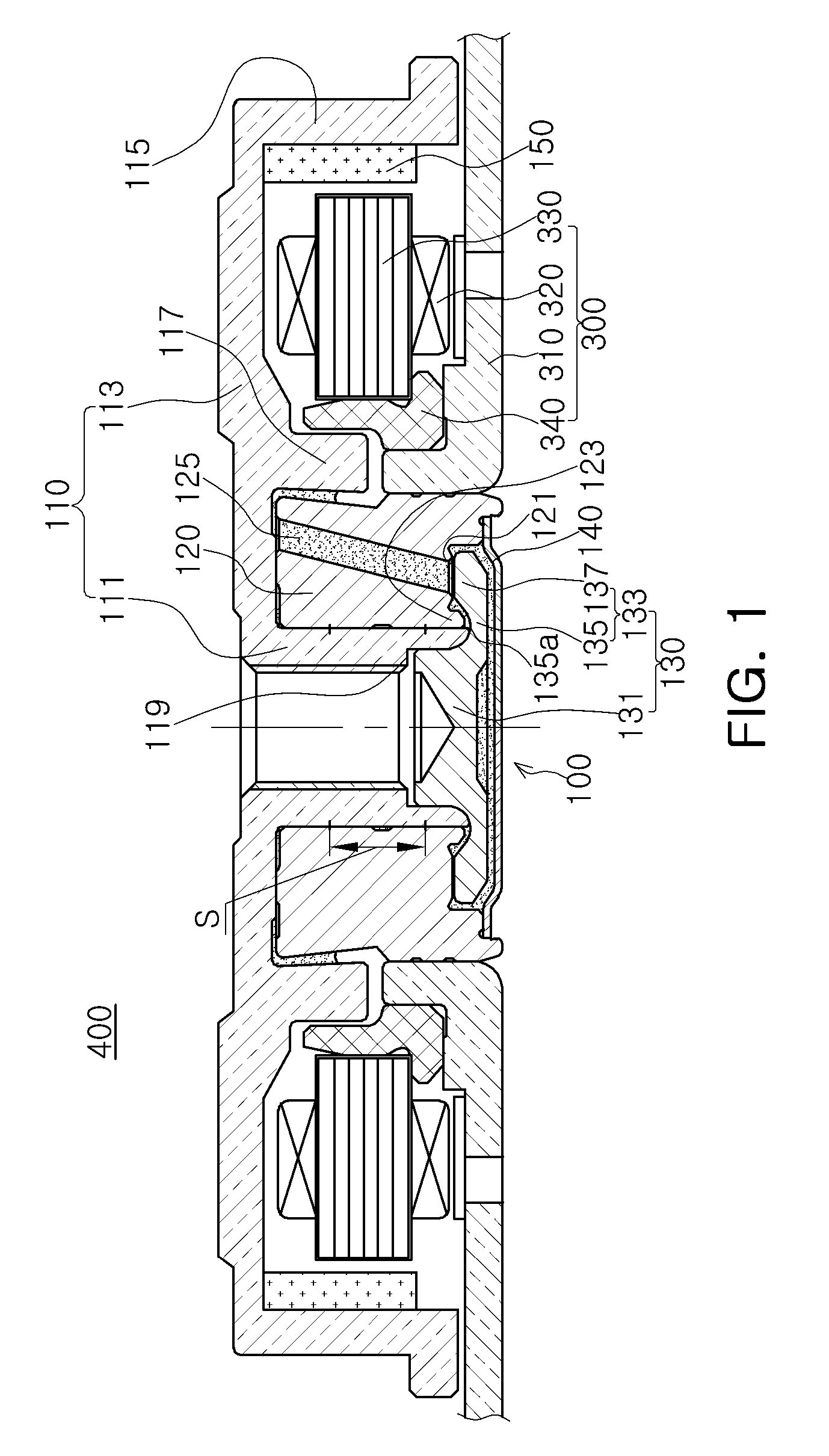
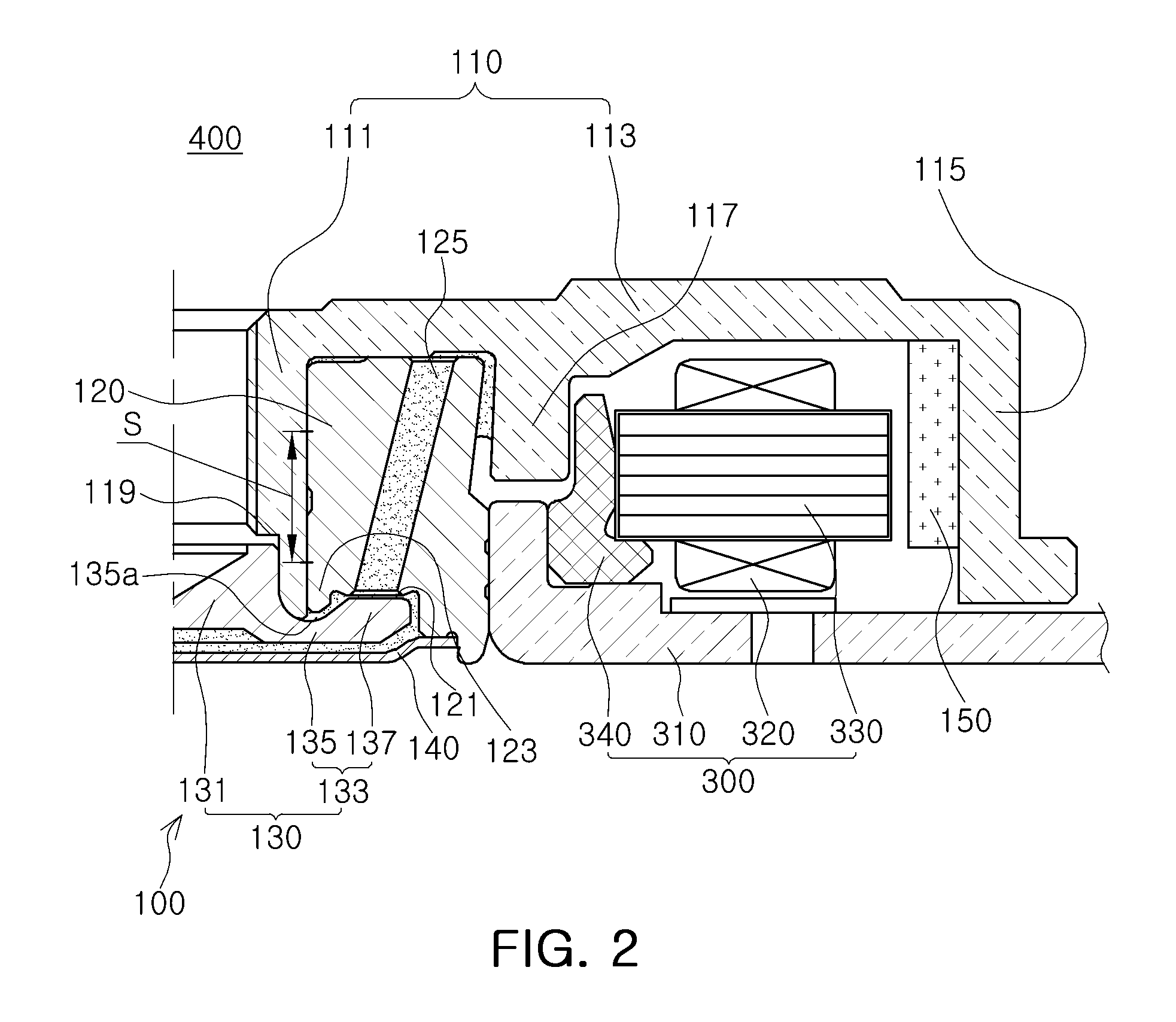
[0048]Referring to FIGS. 1 through 3, a spindle motor 400 according to the invention may include a hydrodynamic bearing assembly 100 and a fixed member, that is, a stator 300.

[0049]First, terms with respect to directions will be defined. As viewed in FIG. 1, an axial direction refers to a vertical direction, based on a shaft 111, and an outer radial direction or an inner radial direction refers to a direction towards an outer edge of the rotating member, based on the shaft 111 or a direction towards the shaft 111, based on the edge of the rotating member.

[0050]The hydrodynamic bearing assembly 100 may include a rotating member 110 including the shaft 111, a sleeve 120, a stopper 130, and a cover plate 140.

[0051]The shaft 111 may configure the rotating member 110, along with a hub base 113 and a magnet support part 115, and may rotate relatively with respect to the fixed member.

[0052]The rotating member 110 may include the shaft 111 inserted into a shaft hole of the sleeve 120, the h...

second embodiment

[0106]That is, in the spindle motor 500 according to the invention, the shaft 111 may be fixed to the shaft housing 160 to configure the rotating member 110 along with the shaft housing 160.

[0107]In this configuration, the shaft housing 160 may be inserted into the shaft hole of the sleeve 120, having a micro clearance between the shaft housing 160 and the shaft hole of the sleeve 120. The micro clearance may be filled with a lubricating fluid, and the rotation of the shaft 110 may be more smoothly supported by a radial dynamic pressure groove (not shown) formed in at least one of an outer diameter of the shaft housing 160 and an inner diameter of the sleeve 120.

[0108]The radial dynamic pressure groove may be formed in the inner circumferential surface of the sleeve 120, the inner portion of the shaft hole of the sleeve 120, and generate pressure so that the shaft housing 160 may smoothly rotate in the state in which the shaft housing 160 is spaced apart from the inner circumferenti...

third embodiment

[0113]In the spindle motor 600 according to the invention, an outer circumferential surface of an upper end portion of the sleeve 120 may be recessed in an inner radial direction.

[0114]Here, the outer circumferential surface of the upper end portion of the sleeve 120 recessed in the inner radial direction may be referred to as a first outer circumferential surface 127 and an outer circumferential surface of a portion of the sleeve 120 adjacent to the first outer circumferential surface 127 may be referred to as a second outer circumferential surface 129.

[0115]Therefore, the first outer circumferential surface 127 may be disposed inwardly of the second outer circumferential surface 129 in the inner radial direction and the outer circumferential surface of the sleeve 120 may be stepped.

[0116]That is, the second outer circumferential surface 129 may protrude in an outer radial direction further than the first outer circumferential surface 127, and the upper end portion of the sleeve 12...


PUM


Abstract

There is provided a spindle motor, including: a rotating member including a shaft having a fixing groove disposed in a lower portion thereof, a hub base extending from an upper end of the shaft in an outer radial direction, and a magnet support part extending from an outer edge of the hub base downwardly in an axial direction; a sleeve rotatably supporting the rotating member; and a stopper including a fixed part inserted into the fixing groove and a flange part extending from an end of the fixed part in the outer radial direction, wherein the flange part includes a groove part formed by being recessed inwardly and an extension part extending from the groove part in the outer radial direction.

Description

CROSS-REFERENCE TO RELATED APPLICATIONS[0001]This application claims the priority of Korean Patent Application No. 10-2013-0028273 filed on Mar. 15, 2013, in the Korean Intellectual Property Office, the disclosure of which is incorporated herein by reference.BACKGROUND OF THE INVENTION[0002]1. Field of the Invention[0003]The present invention relates to a spindle motor and a hard disk drive including the same.[0004]2. Description of the Related Art[0005]A hard disk drive (HDD), an information storage device, reads data stored on a disk or writes data to a disk using a read / write head.[0006]A hard disk drive requires a disk driving device capable of driving the disk. As the disk driving device, a spindle motor is commonly used.[0007]Such a spindle motor uses a hydrodynamic bearing assembly. A shaft, a rotating member of the hydrodynamic bearing assembly, and a sleeve, a fixed member thereof, have a lubricating fluid interposed therebetween, such that the shaft is supported by fluid p...

Claims


Application Information

Patent Timeline
IPC IPC(8): G11B17/02
CPCH02K7/085H02K5/1675G11B19/2018G11B19/2009F16C17/107F16C2370/12G11B19/20
Inventor SMIRNOV, VIATCHESLAV
Owner SAMSUNG ELECTRO MECHANICS CO LTD
Learn More