
Image forming apparatus having dual speed stirring control

a technology of stirring control and stirring chamber, which is applied in the direction of electrographic process apparatus, instruments, optics, etc., can solve the problems of long detection time, long stirring time of the stirring member in the toner container, and long passing time of the detection light through the inside of the toner container correspondingly, so as to achieve the effect of not impairing printing productivity and printing quality

Inactive Publication Date: 2014-09-09
CANON KK
View PDF15 Cites 0 Cited by
  • Summary
  • Abstract
  • Description
  • Claims
  • Application Information

AI Technical Summary

Benefits of technology

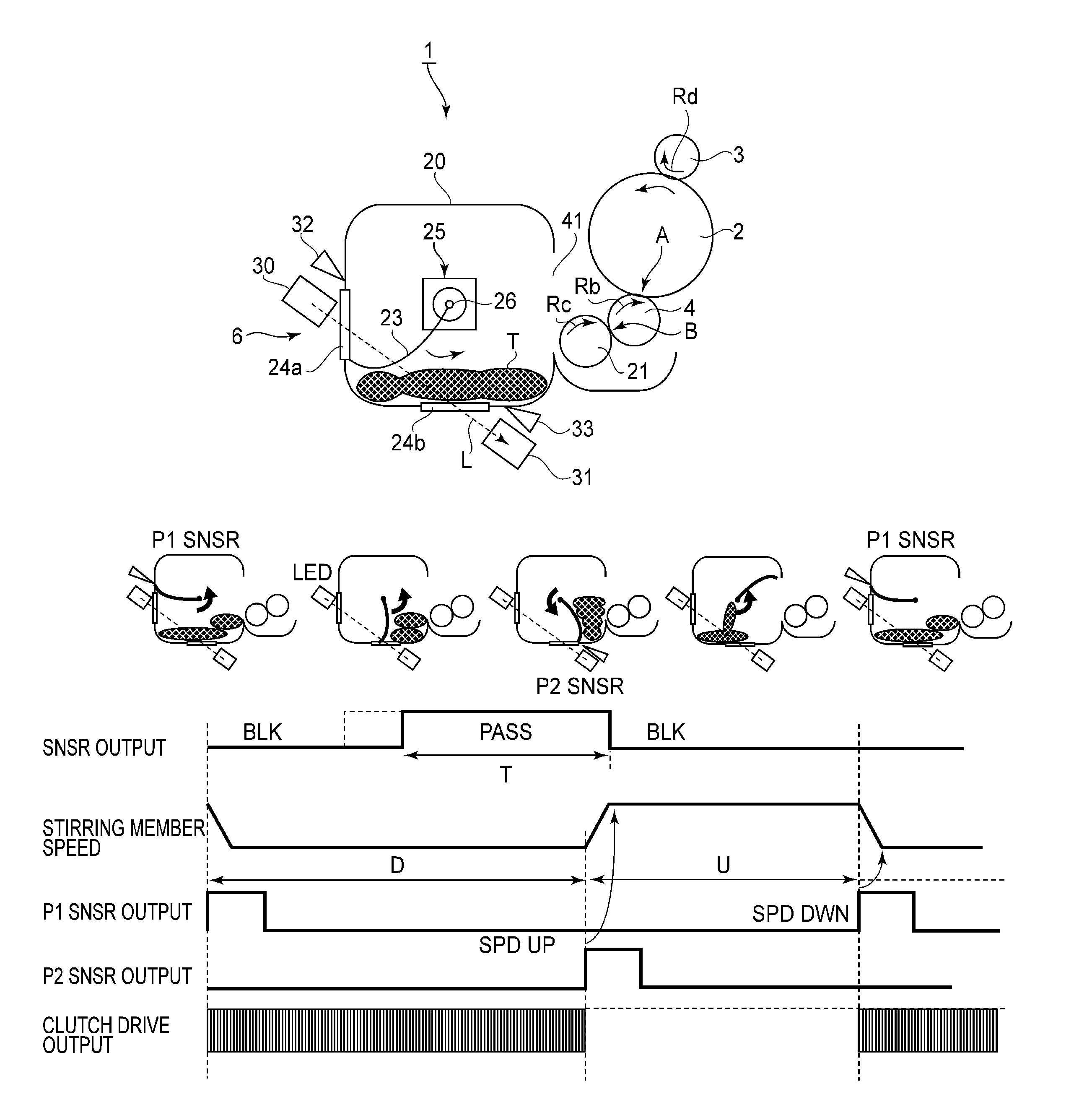
The present invention is aimed at providing an image forming apparatus that can detect the amount of remaining developer accurately and print effectively without affecting productivity and quality, even during high-speed printing when the remaining toner amount is low.

Problems solved by technology

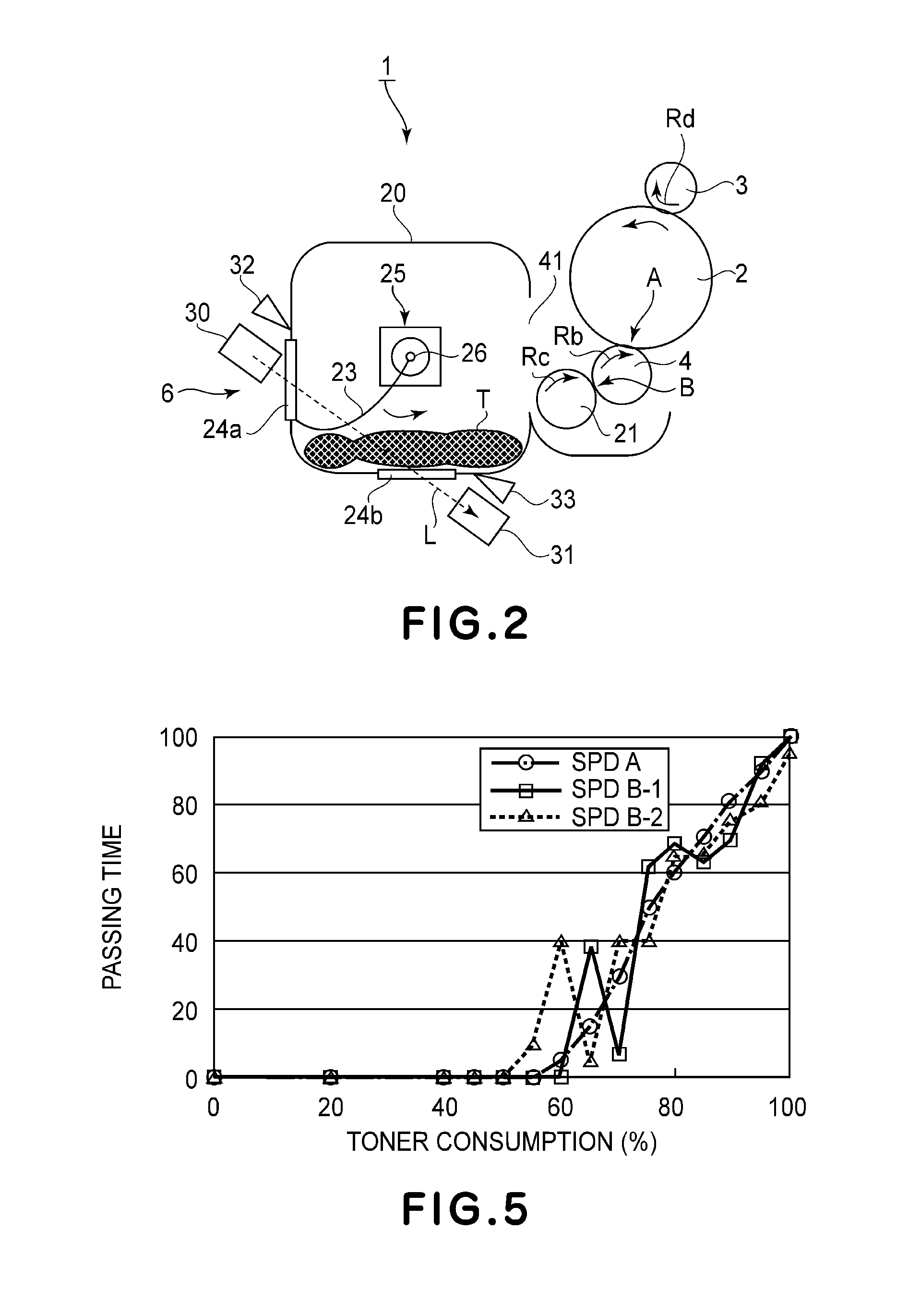
However, when the remaining toner amount is decreased by consumption of the toner in the toner container, an interval from the wiping of the window members with the sheet member until the window members are covered with the toner again is increased, so that a passing time of the detection light through the inside of the toner container correspondingly becomes long.
On the other hand, in the case of a state of the consumption of the toner, the detection light starts to pass through the inside of the toner container and a detection time becomes long.
However, in the electrophotographic image forming apparatus in recent years, with speed-up of a printing speed, a speed of the stirring member in the toner container also becomes high and therefore the toner is scattered in the toner container, so that the light cannot reach the LED for remaining toner amount detection.
For that reason, there is a possibility of an erroneous detection as a toner presence state.
However, in the case where the operation in the fine detection mode in which the remaining toner amount is detected is executed in a state in which the toner is consumed and is small in remaining amount, there is a need to lower a stirring speed.
That is, in the image forming apparatus with high printing productivity, a toner consumption amount of the remaining toner is large and therefore notification of the remaining amount of the toner, capable of being subjected to the printing, to the user becomes inaccurate unless the remaining toner amount is detected frequently.
For that reason, there is a possibility that a period in which the user prepares a next developing device cannot be obtained sufficiently and that a print stop time occurs due to no remaining toner amount.

Method used


Image

  • Image forming apparatus having dual speed stirring control
  • Image forming apparatus having dual speed stirring control
  • Image forming apparatus having dual speed stirring control

Examples


embodiment 1

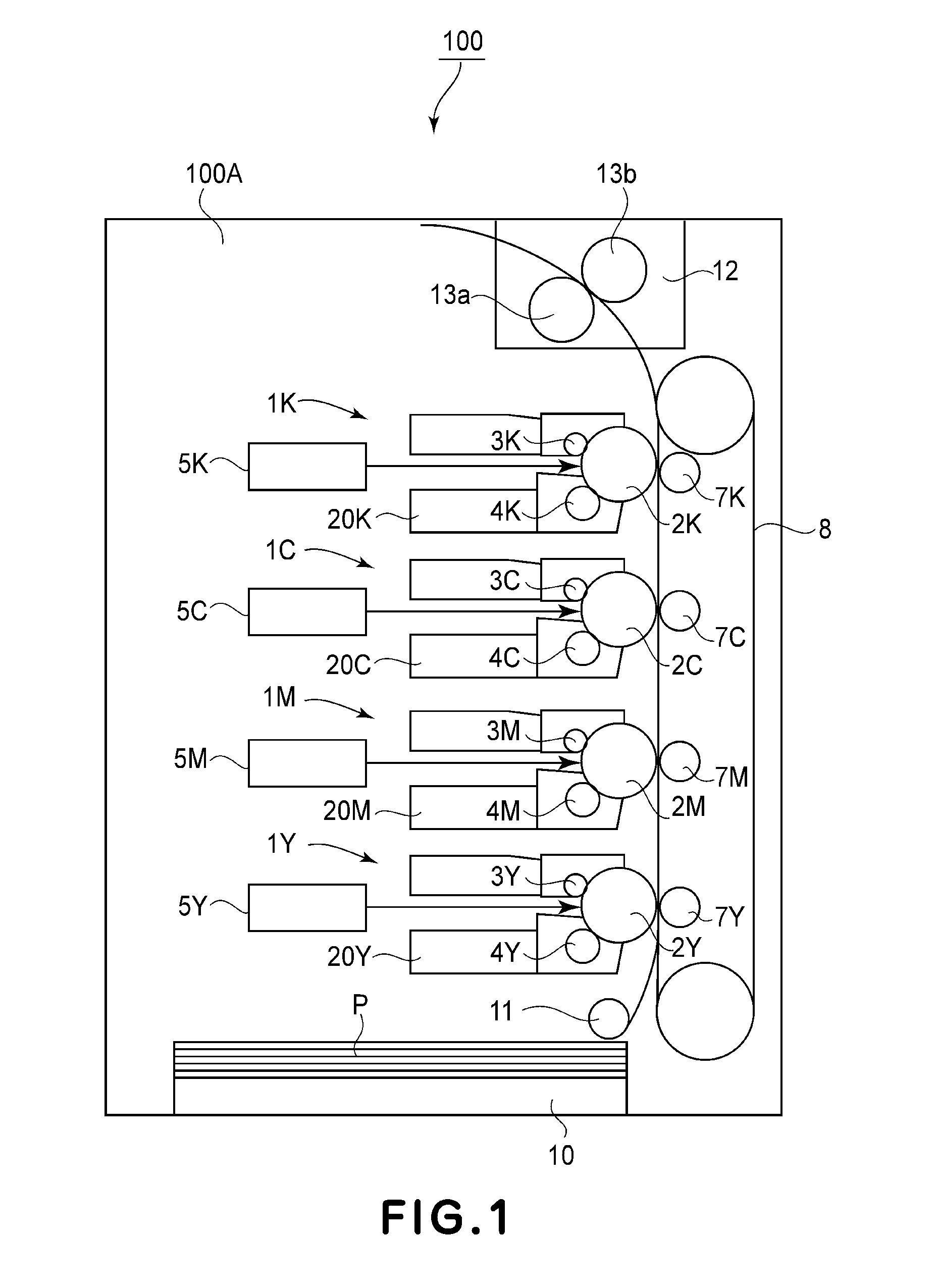
[0034]FIG. 1 shows a schematic structure of the image forming apparatus in this embodiment according to the present invention. According to this embodiment, the image forming apparatus of the present invention is embodied by a laser beam printer of an electrophotographic type (hereinafter simply referred to as a printer). However, the present invention is not limited thereto.

[0035]Referring to FIG. 1, a printer 100 in this embodiment includes process cartridges 1 (1Y, 1M, 1C and 1K) each detachably mountable to a printer main assembly 100A. These four process cartridges 1Y, 1M, 1C and 1K) have the same structure but are different in that images are formed with toners of different colors of yellow (Y), magenta (M), cyan (C) and black (K). The process cartridges 1Y, 1M, 1C and 1K include developer accommodating portions 20 (20Y, 20M, 20C and 20K), image bearing members 2 (2Y, 2M, 2C and 2K), charging means 3 (3Y, 3M, 3C and 3K) and developer carrying members 4 (4Y, 4M, 4C and 4K). Exp...

embodiment 2

[0088]Embodiment 2 will be described with reference to FIGS. 8 and 9. FIGS. 8 and 9 illustrate a drive transmission member 200 for the process cartridge 1.

[0089]A driving force of a main assembly motor 17 provided in the printer main assembly 100A is transmitted from a driving gear to stepped gears 103 (103a, 103b). The driving force from the stepped gears 103 is branched, so that a part of the driving force is transmitted from the stepped gear 103a to a photosensitive drum-side gear 104 and a remaining driving force is transmitted from the stepped gear 103b to a toner container-side gear 105.

[0090]The driving force from the toner container-side gear 105 is further transmitted to gears 106, 107, 108 and 109, so that the developing roller 4 provided coaxially with the gear 109 is driven. The driving force from the gear 107 is transmitted to gears 123 and 124, so that the toner supply roller 21 provided coaxially with the gear 124 is driven.

[0091]On the other hand, as described above,...


PUM


Abstract

An image forming apparatus includes an image bearing member for bearing a latent image, a developer carrying member for developing the latent image with a developer, a developer accommodating portion for accommodating the developer, and a detecting device including a light emitting element and a light receiving element for detecting a remaining developer amount in the developer accommodating portion. In addition, a stirring member stirs the developer by rotating in the developer accommodating portion. The stirring member is rotated in a first period in which the stirring member crosses an optical path of light from the light emitting element toward the light receiving element and a second period in which the stirring member does not cross the optical path of the light. The stirring member is rotated at a first rotational speed in the first period and is rotated at a second rotational speed in the second period higher than the first rotational speed, and wherein the first period and the second period are included in one rotation of the stirring member.

Description

FIELD OF THE INVENTION AND RELATED ART[0001]The present invention relates to an image forming apparatus of an electrophotographic type, such as a copying machine, a printer or a facsimile machine. Particularly, the present invention relates to the image forming apparatus of the electrophotographic type in which a latent image is formed on an image bearing member and is developed with a developer such as toner to obtain a visible image.[0002]For example, in the image forming apparatus of the electrophotographic type such as the printer, a photosensitive drum which is the image bearing member is uniformly charged and is selectively exposed to light to form the latent image, and then the latent image is visualized by fine powdery toner, which is developer, to obtain the visible image (i.e., a toner image). The toner image is transferred onto a recording material and then the transferred toner image is subjected to application of heat and pressure to be fixed on the recording material, ...

Claims


Application Information

Patent Timeline
Patent Type & Authority Patents(United States)
IPC IPC(8): G03G15/08
CPCG03G15/0831G03G15/0827G03G2215/0802G03G2215/0894G03G15/0855G03G15/0856G03G15/0862G03G15/0865
Inventor OTAKE, MASAKI
Owner CANON KK
Learn More