
Projectile containment system

a projectile containment and projectile technology, applied in the direction of bullet catchers, weapons, targets, etc., can solve the problems of air handling equipment otherwise being subject to damage, plate wear, and severe environmental concerns, so as to reduce the wear and tear of plates, efficiently absorb and achieve the effect of absorbing the impact of projectiles on these vanes more efficiently

Inactive Publication Date: 2014-09-09
BULLET TRAP USA
View PDF11 Cites 6 Cited by
  • Summary
  • Abstract
  • Description
  • Claims
  • Application Information

AI Technical Summary

Benefits of technology

[0005]The very rigidity of the steel frame, and of the hardened steel components from which the trap components are made, particularly in the impact area, which may have one or more angled hardened steel plates arranged to slow projectiles These plates are, therefore subject to wearing. There is a need to minimize this excessive wearing away and pitting of the hardened steel that results from the projectiles repeatedly striking the impact area of the trap.
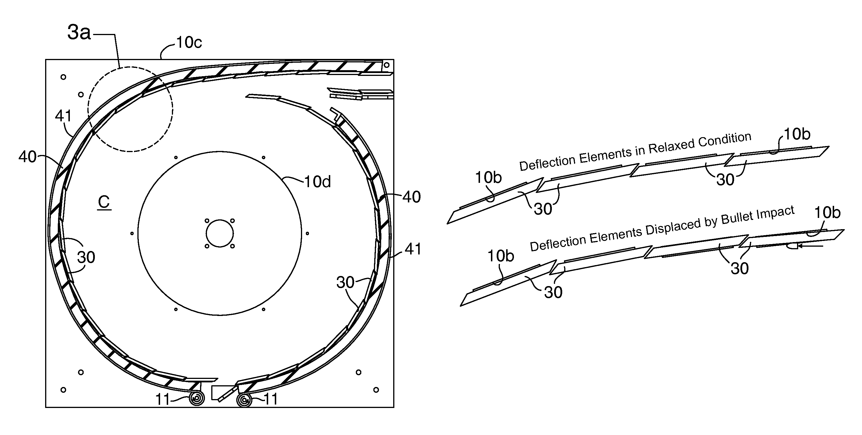
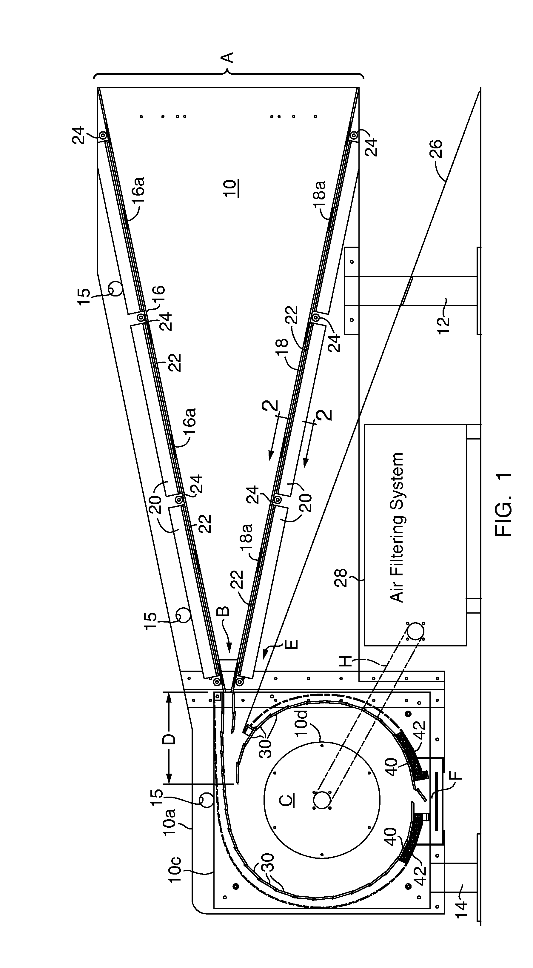
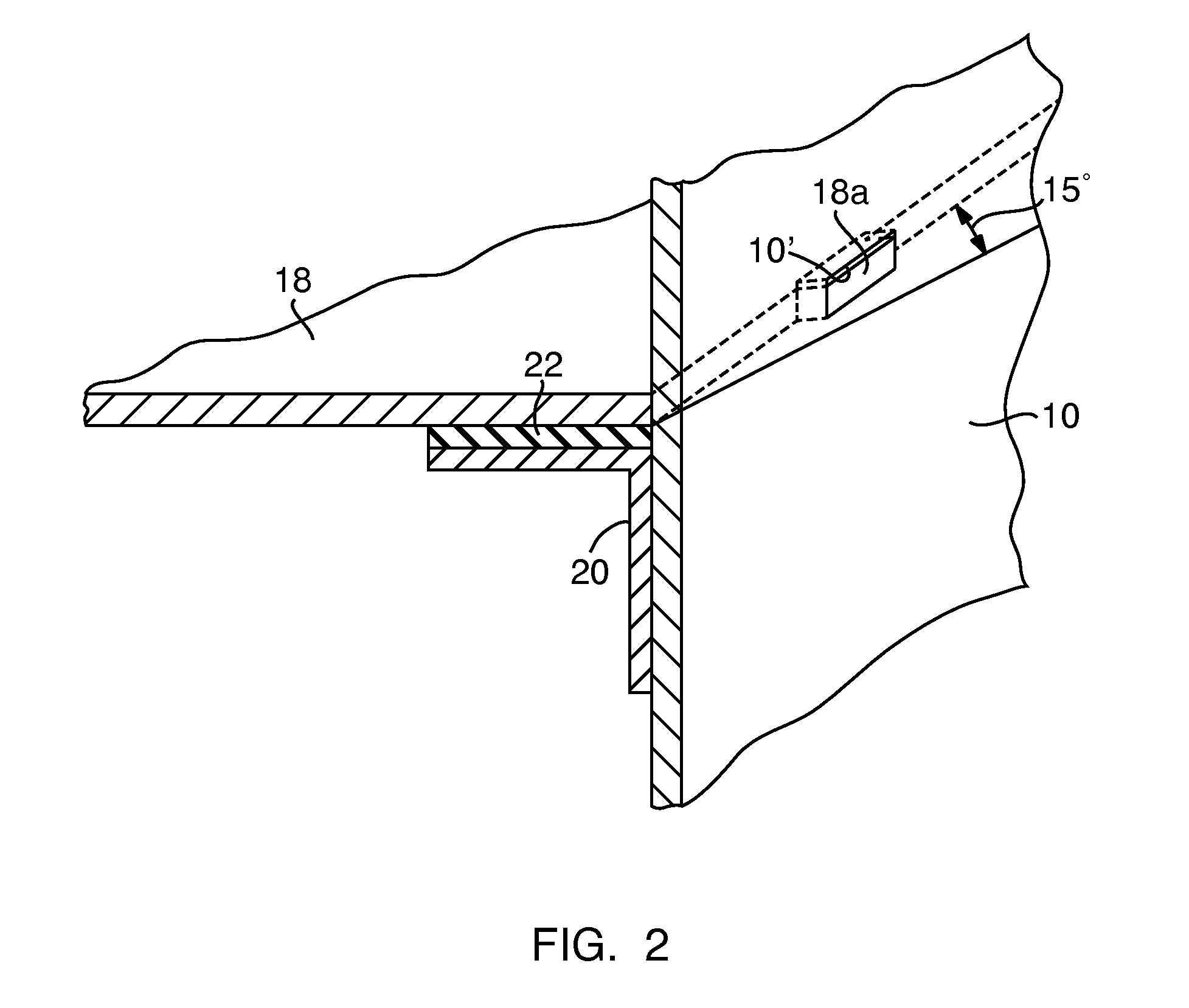
[0006]The present invention provides a hardened steel containment chamber capable of absorbing the energy and momentum of high speed projectiles in an energy efficient way, and without the shock and noise characteristic of prior art bullet traps. The impact area, or boundary, of the containment chamber is defined by laterally extending projectile turning vanes, or strips, that have overlapping beveled edges. Rather than being rigidly mounted these vanes more efficiently absorb projectile impact as a result of providing each hardened steel strip, or vane, in an oversize opening of the steel support structure. More particularly, projecting end portions of these vanes are received in openings of slightly greater depth than the thickness of the vane end portions. The vanes are mounted in overlapping relationship, such that the beveled edges interact causing each vane to effect an adjacent vane when struck by a projectile. As a result, at least two vanes move slightly in reaction to one vane being impacted. The impact of the projectiles on these vanes is thereby absorbed more efficiently. A resilient elastomeric blanket is provided around the outside of the these containment chamber defining vanes, and the blanket is biased radially inwardly, holding the vanes against the inside edges of their respective openings. The beveled vane edges are thus held in engagement with one another, at least in their rest or ready positions, and will be displaced slightly in their respective openings in reacting to the impact and momentum of the projectiles, efficiently absorbing the energy thereof. The vanes are biased inwardly by tensionable straps surrounding the elastomeric blanket. Allowing the vanes to move upon impact also reduces damage to these hardened steel vanes. The biasing force is achieved by wrapping at least one tensionable band or strap at least the impact area of the containment chamber.
[0007]Another advantage to this unique yieldable vane mounting design is the reduction in the ambient noise levels. Reducing the impact forces, between the hardened steel vanes and the lead projectiles, leads to a very significant reduction in the ambient noise level at a firing range. This is a very important result, where the noise can create severe environmental concerns.
[0008]In accordance with a preferred embodiment of the invention, a convergent auxiliary entry passageway is also provided below the convergent projectile passageway described previously. This auxiliary passageway accommodates projectiles passing below the target area at the entry to the main convergent passageway, where the target is mounted. The area, below the containment chamber is rendered safer, and can, therefore, accommodate equipment associated with bullet traps, namely air evacuation and filtering equipment for removal of debris and gasses from the containment chamber. Such air handling equipment would otherwise be subject to damage from errant projectiles that are fired below the target. To define this auxiliary passageway an auxiliary plate cooperates with the underside of the lower convergent passageway plate to define this auxiliary convergent passageway. As so arranged errant projectiles are directed upwardly toward an auxiliary slot in a transition area between an auxiliary throat area at the downstream end of the main convergent passageway, and the containment chamber itself. The upper boundary of this transition area is preferably defined by vanes or strips of hardened steel, similar to those defining the impact area of the containment chamber. The lower boundary of this transition area, or zone, has an auxiliary slot or throat area for this auxiliary convergent passageway, and errant projectiles pass through said auxiliary slot into the containment chamber. The transition area vanes are also mounted in oversize openings and held in by the same, or similar to, the biased blanket described previously, the blanket being biased inwardly to act on these vanes in a manner similar to that of the vanes defining the impact boundary of the containment chamber.

Problems solved by technology

The very rigidity of the steel frame, and of the hardened steel components from which the trap components are made, particularly in the impact area, which may have one or more angled hardened steel plates arranged to slow projectiles These plates are, therefore subject to wearing.
This is a very important result, where the noise can create severe environmental concerns.
Such air handling equipment would otherwise be subject to damage from errant projectiles that are fired below the target.

Method used


Image

  • Projectile containment system
  • Projectile containment system
  • Projectile containment system

Examples


Embodiment Construction

[0016]In it's presently preferred form the bullet trap shown in the drawings will accommodate a single shooter located some distance upstream of the bullet trap. This distance will be dictated mostly by safety considerations, but will also be dictated by the type of firearm used, and by the immediate environment for the shooter's location relative to the bullet trap.

[0017]The bullet trap of FIG. 1 has an open front end A in which a target can be hung, and into which open end the projectiles are fired by the shooter. More particularly, the rectangularly shaped target opening A of the bullet trap has lateral sides, defined by spaced apart vertically extending steel plates 10,10, that are part of a frame which also includes other structural components, such as the legs 12 and 14. These side plates 10,10 are parallel so as not to interfere with projectiles fired into the bullet trap target opening from the shooter's station located upstream thereof. The edges of the target area A are pr...


PUM


Abstract

Steel plates loosely mounted in frame, with neoprene pads between the frame and plates to better absorb the noise and impact from projectiles. The plates are inclined having laterally projecting tabs in openings defined by parallel steel side-walls. A containment chamber communicates with downstream ends of inclined plates by a transition area downstream of the inclined plates. Chamber has projectile impact boundary defined by laterally extending vanes or strips of hardened steel. End portions of vanes fit loosely in openings defined by the chamber side-walls. The vanes have beveled edges that abut one another so movement of adjacent vanes occurs in response to one of these vanes being struck by a projectile. Vanes are biased inwardly toward normal, or rest positions, but can move outwardly when impacted by a projectile. The number of vanes selected to establish angles of incidence for adjacent vanes less than 12 degrees in chamber.

Description

FIELD OF INVENTION[0001]This invention relates to projectile containment systems such as might be required at firing ranges or the like, and deals more particularly with a bullet trap of the type having an open front end in which a target can be provided and a steel structure for decelerating these projectiles and containing the projectiles fired at that target by a shooter located at a station some distance from the target. Such bullet traps are generally made from steel plates that are welded or bolted together in a structure that can include converging upper and lower plates defining a convergent passageway that directs the projectiles from the target area into a containment chamber where they are collected for disposal.PRIOR ART[0002]Bullet traps of such steel plate construction are available from Megitt Training Systems of Suwanee Ga., and from Action Target of Provo Utah. These bullet traps typically have upper and lower converging steel plates that direct the projectiles into...

Claims


Application Information

Patent Timeline
Patent Type & Authority Patents(United States)
IPC IPC(8): F41J13/00
CPCF41J13/00
Inventor LAMOTHE, RICHARD, P.
Owner BULLET TRAP USA
Learn More