
Postal sorting machine for mailpieces and separators, and a method for sorting mailpieces and separators

a sorting machine and mailpiece technology, applied in sorting, instruments, computing, etc., can solve the problem that the method does not make it possible to automatically re-circulate the separators

Inactive Publication Date: 2014-09-02
SOLYSTIC
View PDF2 Cites 0 Cited by
  • Summary
  • Abstract
  • Description
  • Claims
  • Application Information

AI Technical Summary

Benefits of technology

This solution reduces mailpiece sorting time, minimizes the number of separators needed, and optimizes sorting efficiency by automatically managing separators, thus reducing operator workload and handling errors.

Problems solved by technology

That sorting machine and its associated sorting method do not make it possible to re-circulate the separators automatically.

Method used


Image

  • Postal sorting machine for mailpieces and separators, and a method for sorting mailpieces and separators
  • Postal sorting machine for mailpieces and separators, and a method for sorting mailpieces and separators
  • Postal sorting machine for mailpieces and separators, and a method for sorting mailpieces and separators

Examples


first embodiment

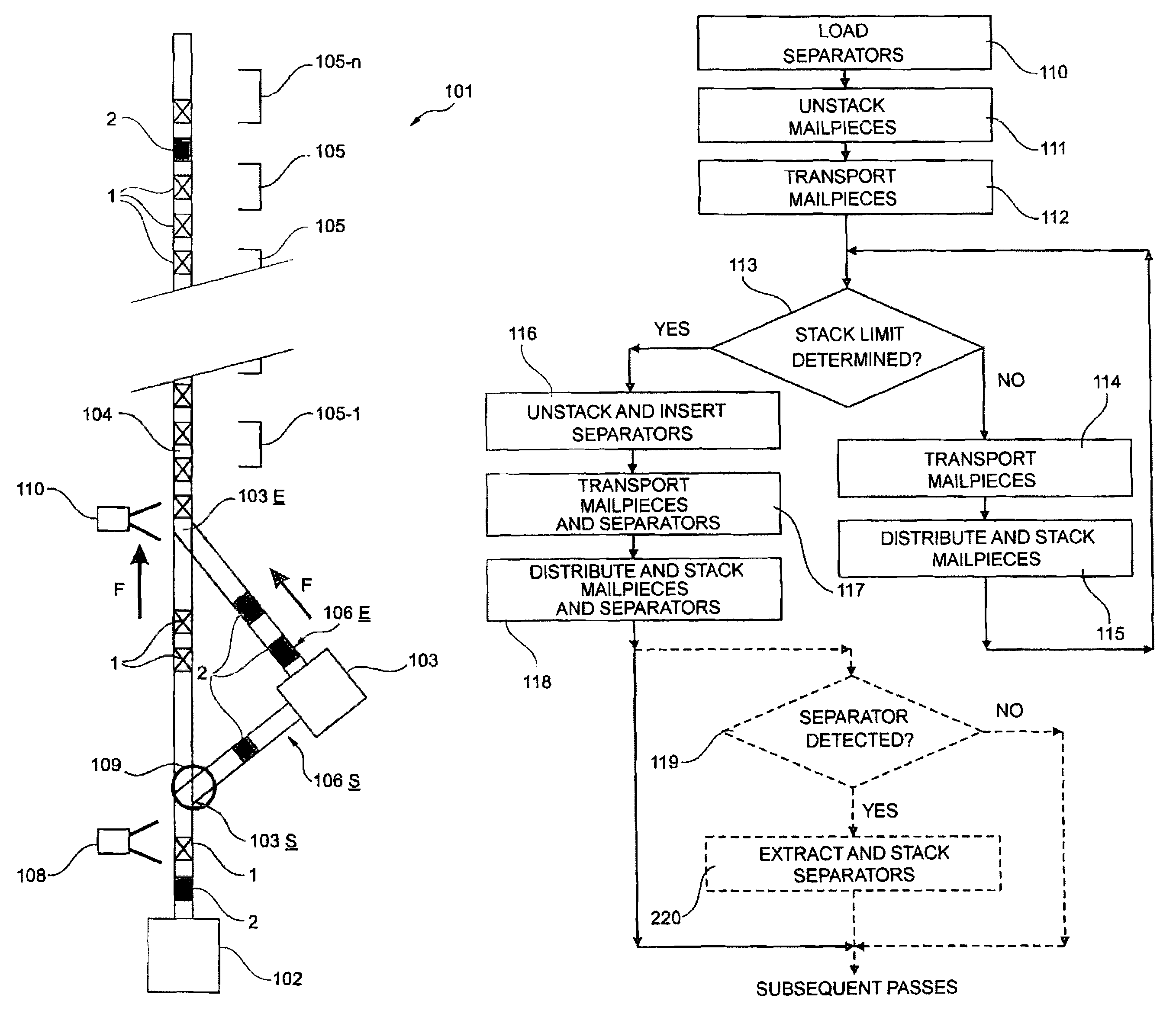
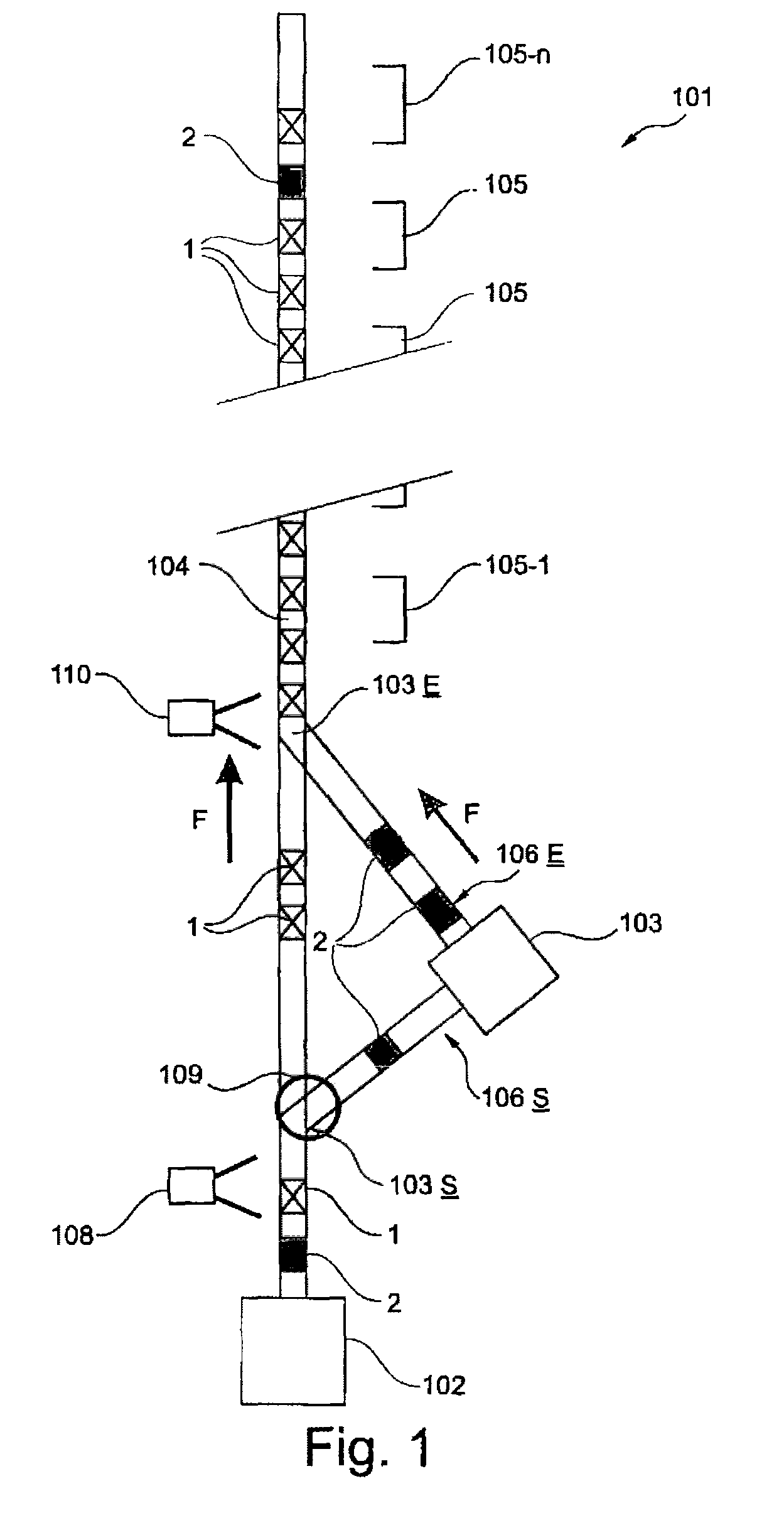
[0024]In the invention and with reference to FIG. 1, the postal sorting machine 101 includes a monitoring and control unit (not shown), a first unstacker 102, a stacker / unstacker 103, a conveyor 104, sorting outlets 105, detection means 108, determination means 110, and guide means 109.

[0025]The monitoring and control unit is of known type and makes it possible to control and regulate various elements of the postal sorting machine 101, such as those described below.

[0026]The first unstacker 102 is of a known combined type, and enables mailpieces 1 and separators 2 that are previously stacked, e.g. manually, to be unstacked automatically. Naturally, this first unstacker 102 is suitable for unstacking a stack of mailpieces 1 that does include any separator 2 and it is controlled by the monitoring and control unit. The first unstacker 102 may unstack the mailpieces 1 with a constant gap, i.e. with a constant distance between the rear edge of the upstream mailpiece 1 and the front edge ...

second embodiment

[0046]FIG. 4 shows the postal sorting machine 201 of the invention. In this figure, the technical elements analogous to the technical elements shown in FIG. 1 are given the same reference numerals, plus 100. The postal sorting machine 201 includes a monitoring and control unit (not shown), a first unstacker 202, and a stacker / unstacker 203, an outgoing ancillary conveyor 206S, an incoming ancillary conveyor 206E, and sorting outlets 205 substantially similar to those of the postal sorting machine 101 of FIG. 1. The direction of movement of the mailpieces 1 and of the separators 2 is indicated by the arrows F. The postal sorting machine 201 also includes a conveyor 204, sorting outlets 205, detection means 208, and determination means 210.

[0047]The conveyor 204 is controlled by the monitoring and control unit so as to transport the mailpieces 1 and the separators 2 to the sorting outlets 205 and so as to distribute them between the various sorting outlets 205. The conveyor 204 is of ...


PUM


Abstract

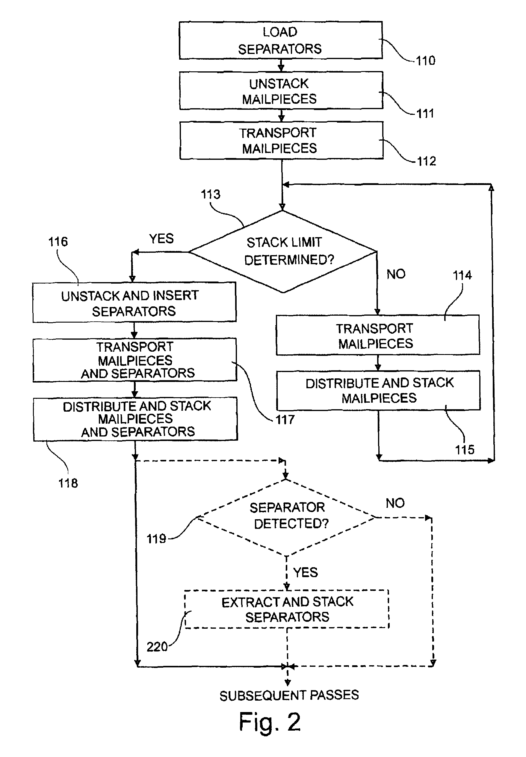
The invention relates to a postal sorting machine (101) for sorting mailpieces (1) and separators (2), which machine includes: sorting outlets (105); a first unstacker (102); a conveyor (104) for distributing said mailpieces (1) and said separators (2) between said sorting outlets (105); a second unstacker (103) for automatically unstacking at least one separator (2) on the basis of at least one predetermined criterion, and for inserting it into the stream of mailpieces (1), said conveyor (104) distributing said reinserted separator (2) to a certain predetermined sorting outlet (105); and a stacker (103) for stacking separators (2), which stacker is interposed between said first unstacker (102) and said second unstacker (103) for the purposes of extracting separators (2), of stacking them, of storing them, and of feeding said second unstacker (103) automatically. The invention also relates to a sorting method using said postal sorting machine (101).

Description

CROSS-REFERENCE TO RELATED APPLICATION(S)[0001]This application is a 35 U.S.C. §371 National Phase Entry Application from PCT / FR2012 / 051612, filed Jul. 9, 2012, designating the United States and also claims the benefit of French Application No. 1156404, filed Jul. 13, 2011, the disclosures of which are incorporated herein by reference in their entirety.TECHNICAL FIELD[0002]The invention relates generally to a postal sorting machine for sorting mailpieces and separators, said postal sorting machine including at least: sorting outlets suitable for receiving said mailpieces and said separators in progressively formed stacks; a first unstacker suitable for automatically unstacking said mailpieces and said separators; a conveyor suitable for transporting said unstacked mailpieces and said unstacked separators towards said sorting outlets, and for distributing them between said sorting outlets on the basis of a predetermined sorting plan; and a second unstacker distinct from said first un...

Claims


Application Information

Patent Timeline
Patent Type & Authority Patents(United States)
IPC IPC(8): G06F7/00
CPCB07C9/00B07C3/00B07C99/00
Inventor GIRODET, FRANCKMADAR, FRANCOISDAUVERGNE, MICKAELCARTAL, BRUNO
Owner SOLYSTIC
Learn More