
Pressure washers including jet pumps

a technology of pressure washers and jet pumps, which is applied in the direction of machines/engines, positive displacement liquid engines, and cleaning using liquids, etc., can solve the problems of reduced flow rate, increased spray intensity, and increased spray intensity, and achieves variable effective

Active Publication Date: 2014-08-26
BRIGGS & STRATTON LLC
View PDF95 Cites 13 Cited by
  • Summary
  • Abstract
  • Description
  • Claims
  • Application Information

AI Technical Summary

Benefits of technology

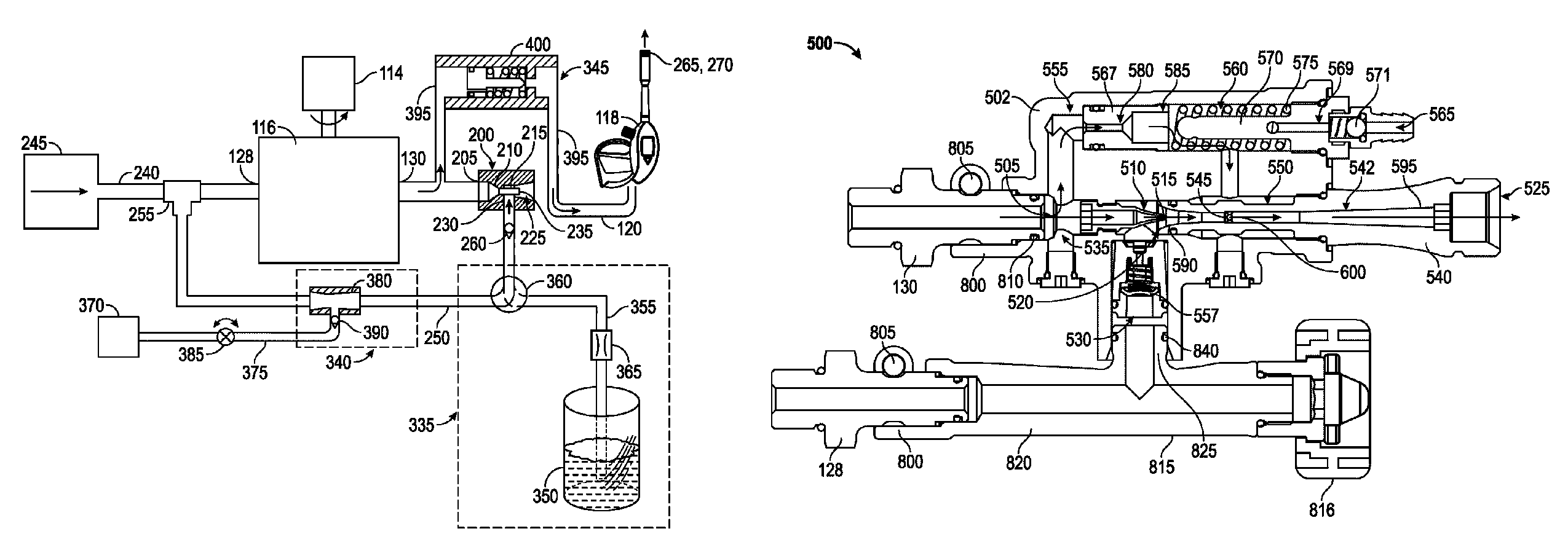
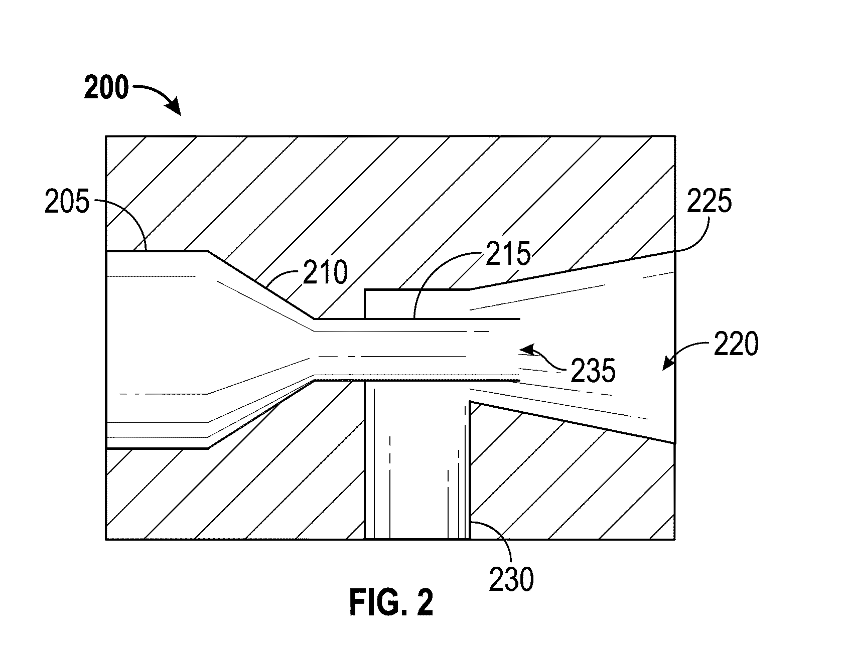
The invention relates to a pressure washer that includes a water pump, a jet pump, and a spray gun. The spray gun has a variable effective flow area that creates back pressure to control the flow of fluid through the jet pump. The back pressure can be adjusted to achieve a high pressure or high flow operating mode. The combined fluid flow of the primary and secondary fluids exiting through the jet pump can be adjusted to achieve the desired back pressure. The invention also includes a bypass conduit and a bypass valve to selectively open or close the bypass flow path. The technical effects of the invention include improved control over the flow of fluid through the jet pump and improved performance in high pressure or high flow operating modes.

Problems solved by technology

Flow rate and water pressure are limited by the water source supplying water to the garden hose sprayer, which may be insufficient for some applications.
The water pressure is greatly increased relative to a typical garden hose sprayer, but the flow rate may be decreased and the intensity of the spray may be too great from some applications, such as cleaning windows and watering plants.
However, the water pressure increase by the garden hose booster is typically less than that of a pressure washer.

Method used


Image

  • Pressure washers including jet pumps
  • Pressure washers including jet pumps
  • Pressure washers including jet pumps

Examples


Embodiment Construction

[0039]Before turning to the figures, which illustrate the exemplary embodiments in detail, it should be understood that the application is not limited to the details or methodology set forth in the description or illustrated in the figures. It should also be understood that the terminology is for the purpose of description only and should not be regarded as limiting.

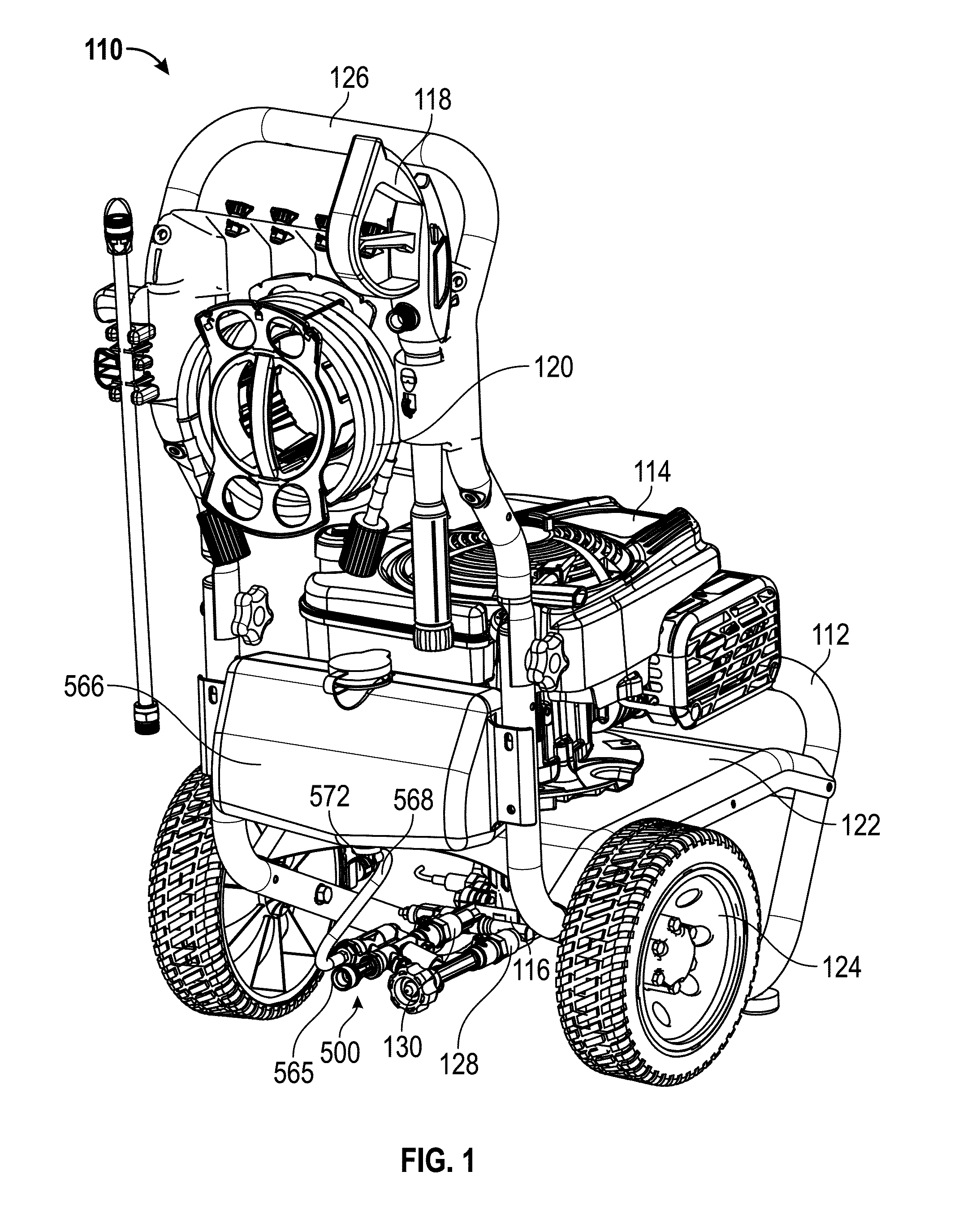
[0040]Referring to FIG. 1, a pressure washer 110 includes a frame 112 supporting a prime mover 114, such as an internal combustion engine, and a water pump 116 (e.g., positive displacement pump, piston water pump, axial cam pump) configured to be connected to a spray gun 118 with a delivery conduit 120 (e.g., a high-pressure hose). In other embodiments, an electric motor is used as the prime mover 114. In some embodiments, the prime mover 114 is fastened to the top of a base plate 122 of the frame 112 and the water pump 116 is mounted below the base plate 122 and connected to a power takeoff of the prime mover 114 via a ...


PUM


Abstract

A pressure washer includes a prime mover, a water pump, the water pump including a pump inlet for receiving fluid from a fluid source and a pump outlet for supplying a pressurized primary fluid, a jet pump including a primary fluid inlet fluidly coupled to the pump outlet, a secondary fluid inlet, and a fluid outlet, and a spray gun configured to be fluidly coupled to the fluid outlet of the jet pump, the spray gun including a spray gun outlet having a variable effective flow area. Wherein, in operation, in a high pressure operating mode, the pressurized primary fluid flows through the jet pump and exits through the fluid outlet of the jet pump, and in a high flow operating mode, the pressurized primary fluid flows through the jet pump and entrains a secondary fluid supplied through the secondary fluid inlet, resulting in a combined fluid flow.

Description

CROSS-REFERENCE TO RELATED PATENT APPLICATIONS[0001]This application claims the benefit of U.S. Provisional Application No. 61 / 679,030, filed Aug. 2, 2012, U.S. Provisional Application No. 61 / 745,461, filed Dec. 21, 2012, and U.S. Provisional Application No. 61 / 780,584, filed Mar. 13, 2013, all of which are incorporated herein by reference in their entireties.BACKGROUND[0002]The present invention relates generally to a device that pressurizes and sprays water, such as for outdoor cleaning applications. More specifically, the present invention relates to a device that is configured to condition the flow of water, such as by changing the flow rate, the water pressure, the shape of the flow exiting the device, or other characteristics of the flow, in order to customize performance of the device to one of a variety of outdoor cleaning tasks.[0003]Different water spraying devices are used for different applications. Garden hose sprayers may be attached to garden hoses and typically inclu...

Claims


Application Information

Patent Timeline
Patent Type & Authority Patents(United States)
IPC IPC(8): B08B3/02F04F5/48B01F5/04F04F5/04F04F5/00F04F5/46
CPCB05B7/0408B08B3/026B08B2203/0217F04F5/00F04F5/12B01F5/043B01F5/0498B01F5/0428B01F25/31243B01F25/31242B01F25/32B01F2101/305B08B2203/0205
Inventor RAASCH, JASON, J.
Owner BRIGGS & STRATTON LLC
Learn More