
Image forming apparatus

a technology of image forming apparatus and forming plate, which is applied in the direction of electrographic process apparatus, instruments, optics, etc., can solve the problems of inability to achieve desired transferability, inability to transfer toner well on embossed surfaces, and inability to transfer toner properly. achieve good transferability

Active Publication Date: 2014-07-22
RICOH KK
View PDF47 Cites 8 Cited by
  • Summary
  • Abstract
  • Description
  • Claims
  • Application Information

AI Technical Summary

Benefits of technology

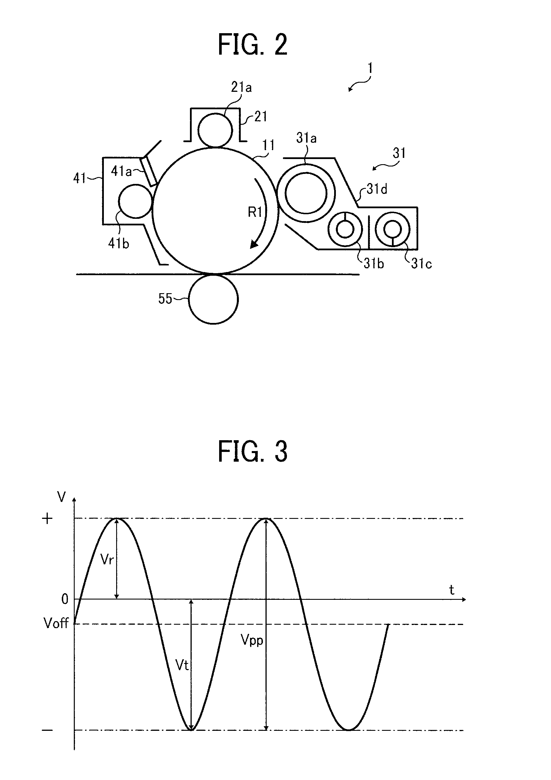
[0008]In another approach, in order to prevent dropouts and obtain desired imaging quality, an alternating current (AC) voltage is superimposed on a direct current (DC) voltage to form a transfer bias. For example, in JP-2006-267486-A, a superimposed bias, in which an AC voltage is superimposed on a DC voltage, is used as the transfer bias, and the surface of the recording medium is charged with a polarity opposite that of the toner in accordance with the roughness of the surface prior to transfer.

Problems solved by technology

However, toner does not transfer well to such embossed surfaces, in particular the recessed portions of the surface.
This improper transfer of the toner appears as dropouts or white spots in the resulting output image.
However, the desired transferability is still not achieved if the recessed portions are relatively deep.
Although the above-described approaches are advantageous and generally effective for the intended purpose, the level of the superimposed AC voltage is relatively low so that the toner does not transfer well onto the recessed portions of the recording media.

Method used


Image

  • Image forming apparatus
  • Image forming apparatus
  • Image forming apparatus

Examples


Embodiment Construction

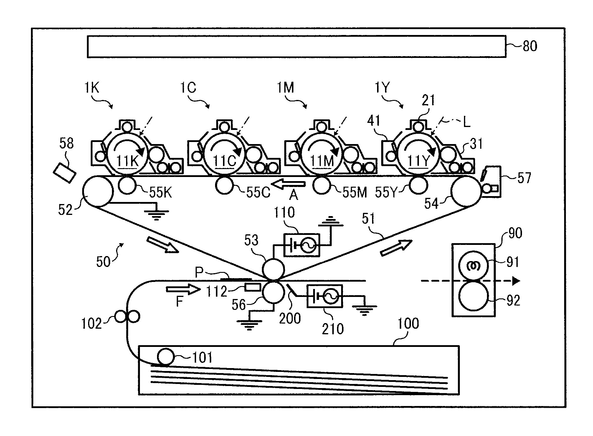
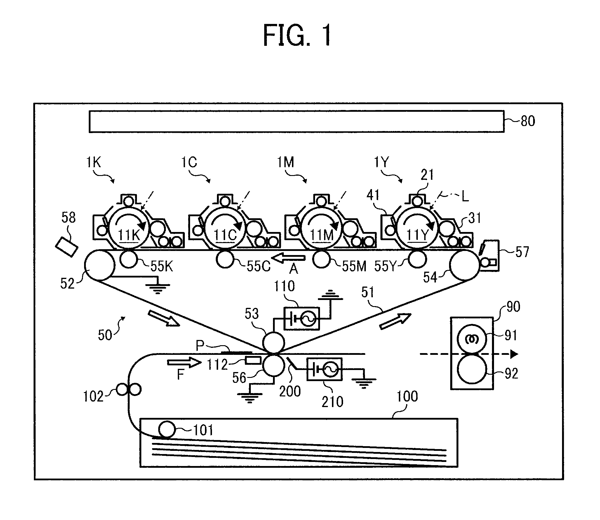
[0019]A description is now given of illustrative embodiments of the present invention. It should be noted that although such terms as first, second, etc. may be used herein to describe various elements, components, regions, layers and / or sections, it should be understood that such elements, components, regions, layers and / or sections are not limited thereby because such terms are relative, that is, used only to distinguish one element, component, region, layer or section from another region, layer or section. Thus, for example, a first element, component, region, layer or section discussed below could be termed a second element, component, region, layer or section without departing from the teachings of this disclosure.

[0020]In addition, it should be noted that the terminology used herein is for the purpose of describing particular embodiments only and is not intended to be limiting of this disclosure. Thus, for example, as used herein, the singular forms “a”, “an” and “the” are int...


PUM


Abstract

An image forming apparatus includes a transfer device to transfer a toner image formed on an image bearing member onto a recording medium, a sheet separation device to separate the recording medium from the image bearing member, a sheet separation bias application device to apply to the sheet separation device a sheet separation bias in which an alternating current (AC) component is superimposed on a direct current (DC) component, and a transfer bias application device to selectively apply to the transfer device one of a DC transfer bias having a DC component and a superimposed transfer bias in which an AC component is superimposed on a DC component. Upon application of the superimposed transfer bias to the transfer device, the sheet separation bias applied to the sheet separation device is changed from the sheet separation bias applied upon application of the DC transfer bias to the transfer device.

Description

CROSS-REFERENCE TO RELATED APPLICATION[0001]This patent application is based on and claims priority pursuant to 35 U.S.C. §119 to Japanese Patent Application No. 2011-199245, filed on Sep. 13, 2011 in the Japanese Patent Office, the entire disclosure of which is hereby incorporated by reference herein.BACKGROUND OF THE INVENTION[0002]1. Field of the Invention[0003]Exemplary aspects of the present invention generally relate to an electrophotographic image forming apparatus, such as a copier, a facsimile machine, a printer, or a multi-functional system including a combination thereof.[0004]2. Description of the Related Art[0005]Related-art image forming apparatuses, such as copiers, facsimile machines, printers, or multifunction printers having at least one of copying, printing, scanning, and facsimile capabilities, typically form an image on a recording medium according to image data. Thus, for example, a charger uniformly charges a surface of an image bearing member (which may, for ...

Claims


Application Information

Patent Timeline
Patent Type & Authority Patents(United States)
IPC IPC(8): G03G15/14G03G15/00G03G15/16
CPCG03G15/6535G03G15/1675G03G2215/00776G03G2215/00772G03G15/6532
Inventor NAKAMURA, KEIGOISHII, HIROKAZUSHIMIZU, YASUNOBUOGIYAMA, HIROMITANAKA, SHINYA
Owner RICOH KK
Learn More