Shake correcting system with slide mechanism which allows unit to be freely movable, lens barrel, imaging device and hand-held data terminal
a technology of slide mechanism and shake corrector, which is applied in the field of shake corrector, can solve the problems of increasing the thickness of the corrector in the optical axis direction, the friction resistance between the guide shaft and the movable frame is increased, and the size of the corrector is increased. , to achieve the effect of reducing the necessary electric power and reducing the load
- Summary
- Abstract
- Description
- Claims
- Application Information
AI Technical Summary
Benefits of technology
Problems solved by technology
Method used
Image
Examples
first embodiment
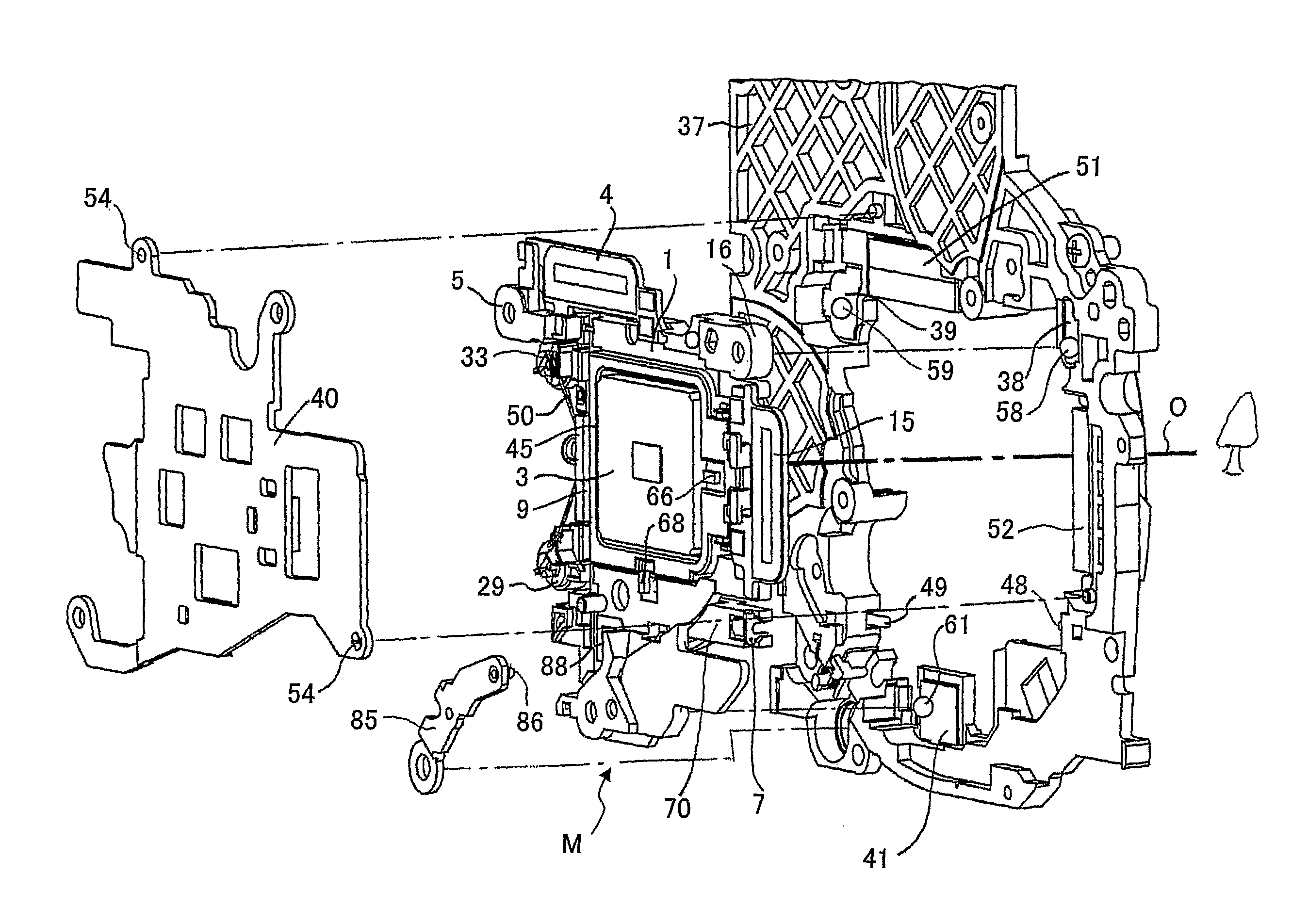
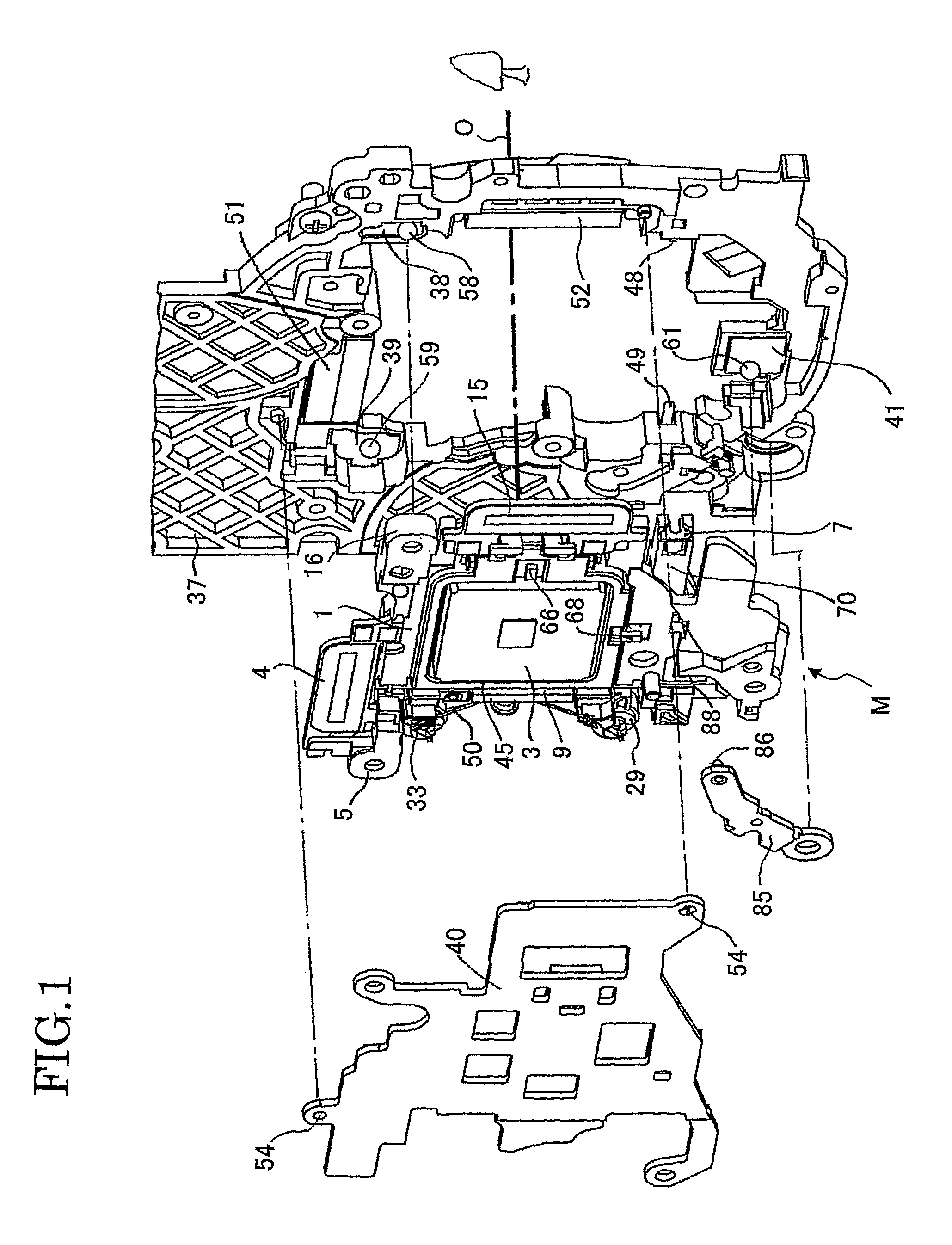
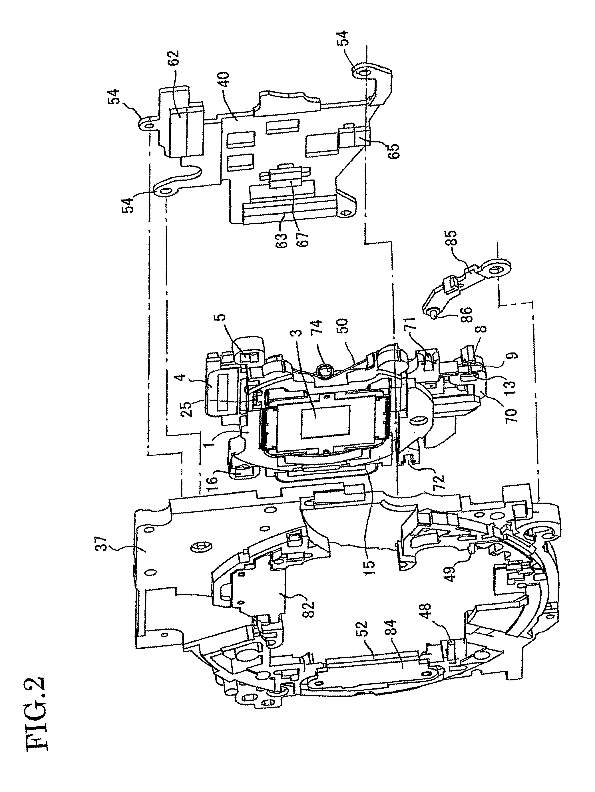
[0075]The shake correcting system according to the first embodiment will be described with reference to FIG. 1 to FIG. 20. The shake correcting system comprises a base 37 to place the movable frame 1 between the base 37 and a plate-like back yolk 40 and movably support it in a plane orthogonal to the optical axis. The movable frame 1 integrally holds an image sensor frame 45 on which an image sensor 3 as a CCD is mounted via a later described inclination adjust mechanism. The base has openings in which various elements as the movable frame 1, the image sensor frame 45 and the image sensor 3 are placed. The back yolk 40 includes a number of holes 54 into which protrusions of the base 37 are fitted, with the movable frame 5 placed between the back yolk 40 and the base 37. In FIG. 1 the optical axis is indicated by an alphabetic code, “O” and the right side is a subject side.
[0076]The movable frame 1 is movable along an intermediate shaft 9 integrally vertically standing on a rotation ...
second embodiment
[0103]Next, the second embodiment of the present invention is described with reference to FIG. 22 to FIG. 26. A difference between the first and second embodiments is in the structure of the ball movement restrictor 10. In the first embodiment the ball movement restrictor is provided in the expanding portion, a lower position than the main portion of the restrictor 70, and the ball receiver plate 41 is positioned in association with the ball movement restrictors 10. This is to stably support the movable frame 1 by keeping the three portions of the slide mechanism away from each other. However, such a configuration has a disadvantage of increasing the size of the image correcting system in the optical axis direction. The second embodiment is for resolving the disadvantage. The rest of the structure is mostly the same as that of the first embodiment and the same components and functions are given the same numeric codes, so that a description thereof will be omitted.
[0104]In the second...
third embodiment
[0110]A shake correction system according to the third embodiment comprises a stopper (tilt prevention mechanism) to reduce or eliminate rotary force on the image sensor, and is described in detail with reference to FIGS. 27 to 30. In FIG. 27, Z axis is the optical axis of an optical imaging system, and X and Y axes are orthogonal to Z axis and to each other. X axis is a moving direction of the horizontal shafts 48, 49 of the first embodiment and Y axis is a moving direction of the intermediate shaft 9. A position in which the center of the X, Y axes intersects with the Z axis as the optical axis is an original position of the movable frame 1 for shake correction.
[0111]In FIGS. 28 to 30, the movable frame 1 integrally holding the image sensor on the image sensor frame includes two protrusions 91 on a base 100 of the cam elements 29, 33. The protrusions 91 face planar walls 92 of the base 37 with a predetermined interval. The protrusions 91 and walls 92 constitute stoppers which limi...
PUM
 Abstract
Description
Claims
Application Information
 - R&D Engineer
- R&D Manager
- IP Professional
- Industry Leading Data Capabilities
- Powerful AI technology
- Patent DNA Extraction
Browse by: Latest US Patents, China's latest patents, Technical Efficacy Thesaurus, Application Domain, Technology Topic, Popular Technical Reports.
© 2024 PatSnap. All rights reserved.Legal|Privacy policy|Modern Slavery Act Transparency Statement|Sitemap|About US| Contact US: help@patsnap.com


