
System, method, and apparatus for electric power grid and network management of grid elements

a technology of electric power grid and network management, applied in the field of electric power management systems, can solve problems such as power that cannot be compensated for by the grid, unsatisfactory security, and more likely to be susceptible to hostile or malicious acts

Active Publication Date: 2014-06-24
CAUSAM ENERGY INC
View PDF45 Cites 56 Cited by
  • Summary
  • Abstract
  • Description
  • Claims
  • Application Information

AI Technical Summary

Benefits of technology

The present invention provides a system, method, and apparatus for managing and registering electric power grid elements. These grid elements can be transformed into active elements after initial registration with the system, which allows them to function within the electric power grid. The system can communicate with the grid elements through a network, and can manage information associated with the grid elements and their activities. The transformation process includes authentication, registration, and management of control devices associated with the grid. The invention also provides an apparatus for smart electric power grid communication, which includes a grid element constructed for network-based communication with a server. The grid element can automatically become an active element within the electric power grid upon initial connection with the server. The invention allows for efficient management and control of the electric power grid, as well as tracking and managing the activities of grid elements.

Problems solved by technology

Existing power management systems, including those utilizing radio subsystems that operate in unlicensed and uncontrolled spectrum bands such as the FCC is in bands, do not address security problems adequately and thus are more likely susceptible to hostile or malicious acts.
This would occur when renewable energy such as solar or wind is added to the grid, resulting in power that cannot be compensated for by the grid.
This could occur, for example, on very windy days.
When this happens, utilities or market participant, grid operator, EMS, or equivalent are faced with the problem of what to do with the excess energy.

Method used


Image

  • System, method, and apparatus for electric power grid and network management of grid elements
  • System, method, and apparatus for electric power grid and network management of grid elements
  • System, method, and apparatus for electric power grid and network management of grid elements

Examples


Embodiment Construction

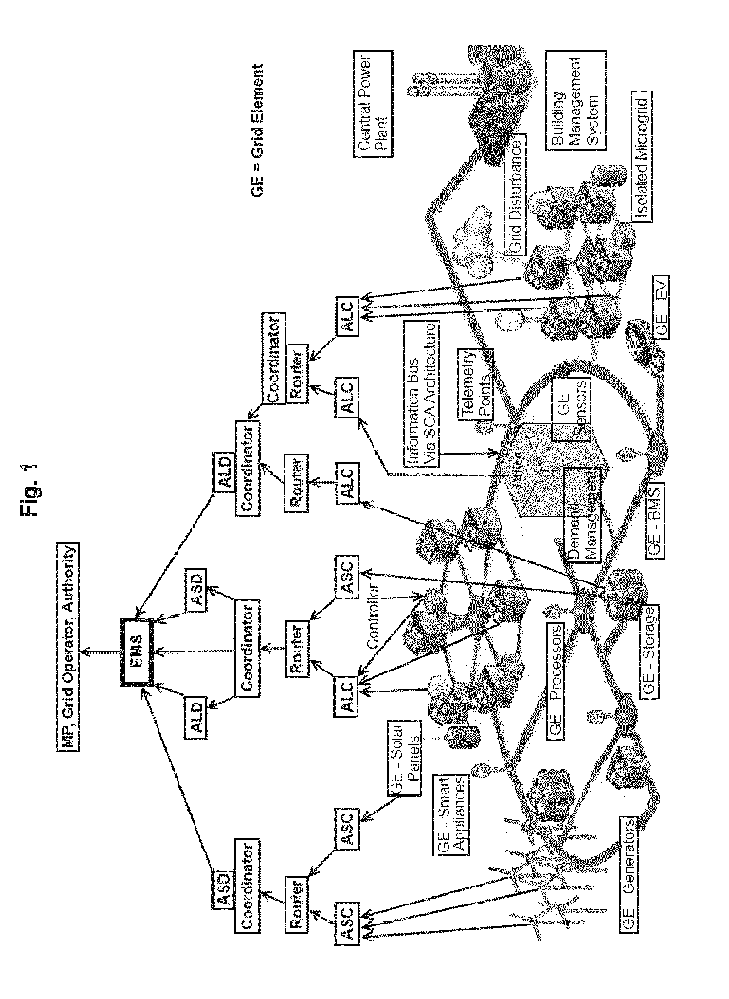
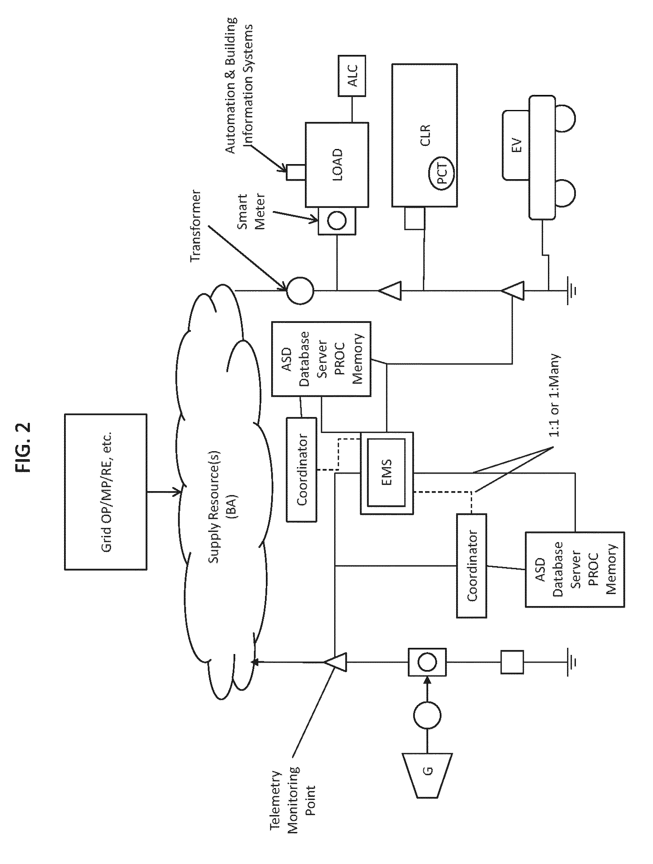
[0088]The present invention provides systems, methods, and apparatus embodiments for electric power grid and network registration and management of grid elements. Accordingly, grid elements are transformed into active grid elements following initial registration of each grid element with the system, preferably through network-based communication between the grid elements and a Coordinator. Also preferably, messaging is managed through a network by a Coordinator using IP-based messaging for communication with the active grid elements, with the energy management system (EMS), and with the utilities, market participants, and / or grid operators subsystems necessary for electric grid operations. Following initial registration, the multiplicity of active grid elements function in the grid for reporting, telemetry, command & control, status, normal or emergency electric grid operations in the generation subsystems (of all generation capacities and types) that supply capacity / energy to the e...


PUM


Abstract

Systems, methods, and apparatus embodiments for electric power grid and network registration and management of active grid elements. Grid elements are transformed into active grid elements following initial registration of each grid element with the system, preferably through network-based communication between the grid elements and a coordinator, either in coordination with or outside of an IP-based communications network router. A multiplicity of active grid elements function in the grid for supply capacity, supply and / or load curtailment as supply or capacity. Also preferably, messaging is managed through a network by a Coordinator using IP messaging for communication with the grid elements, with the energy management system (EMS), and with the utilities, market participants, and / or grid operators.

Description

CROSS-REFERENCES TO RELATED APPLICATIONS[0001]This application is a continuation of application Ser. No. 13 / 757,772, filed Feb. 2, 2013, which is a continuation of application Ser. No. 13 / 563,535, filed Jul. 31, 2012, both of which are incorporated herein by reference in their entirety.BACKGROUND OF THE INVENTION[0002]1. Field of the Invention[0003]The present invention relates generally to the field of electrical power management systems, and more particularly, to systems, methods, and apparatus embodiments for electric power grid and network registration and management of grid elements.[0004]2. Description of Related Art[0005]Generally, electric power management systems for an electric power grid are known. However, most prior art systems and methods apply to normal grid management, macro (large) generation subsystems, transmission subsystems for transporting high voltage power bulk power to distributions systems where it is sent to end customers. Prior art to control power load c...

Claims


Application Information

Patent Timeline
Patent Type & Authority Patents(United States)
IPC IPC(8): G05D9/00G05D17/00G06F1/00G08B23/00G05D11/00G05D5/00G05D3/12
CPCH02J3/14G05B19/02G05B13/02G05F1/66G05B15/02H02J13/0062H04L67/10Y02B70/3225Y04S20/222Y04S20/224H02J3/00H02J2203/20H02J2310/12H02J13/00016H02J13/00004H02J13/00028H02J13/00034Y02E60/00Y04S40/20Y04S40/12H02J2203/10H02J13/00026H02J13/00006G05B11/01G05B19/042G05B2219/40458G05B13/0255
Inventor FORBES, JR., JOSEPH, W.
Owner CAUSAM ENERGY INC
Learn More