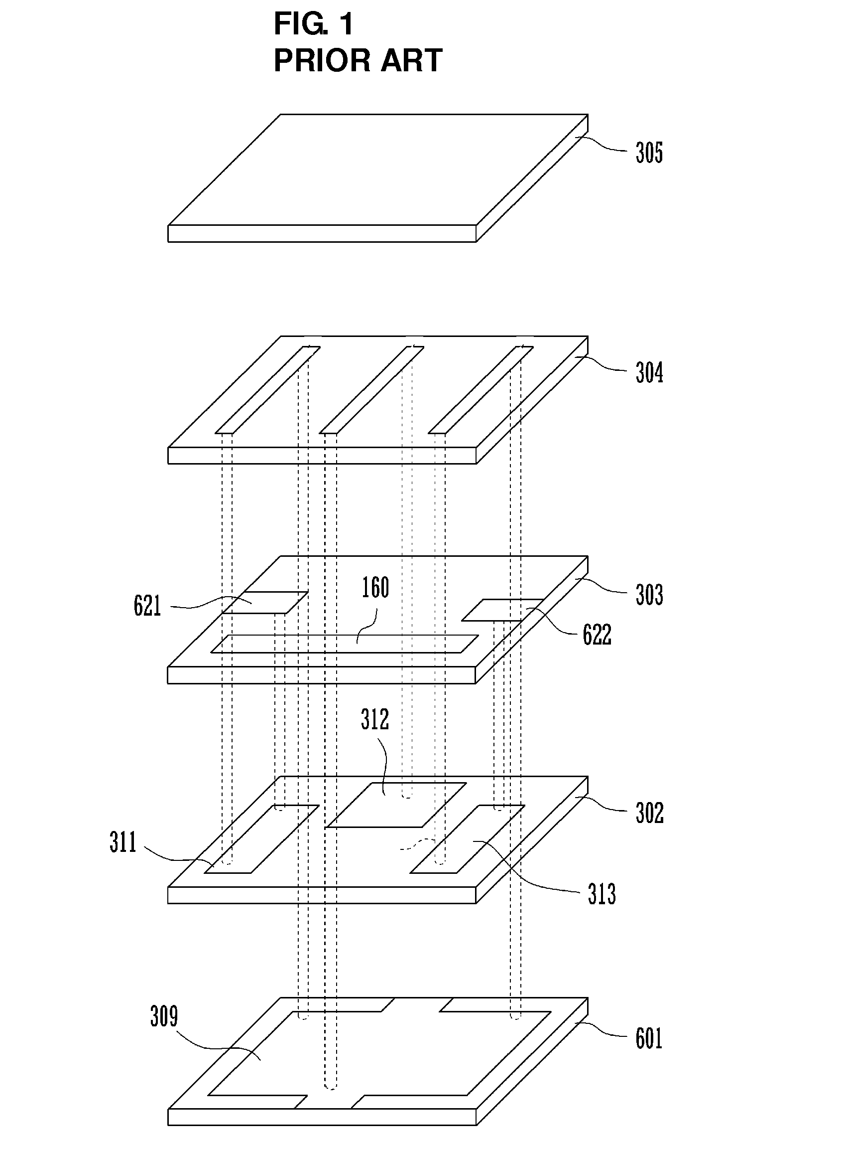
Multilayer band-pass filter
a band-pass filter and multi-layer technology, applied in the field of multi-layer filters, can solve the problems of reducing the q of the filter, deteriorating the attenuation characteristics, and difficult miniaturization of the device, and achieves the effects of excellent filter characteristics, stable characteristics, and easy design of the impedance of each inductor
- Summary
- Abstract
- Description
- Claims
- Application Information
AI Technical Summary
Benefits of technology
Problems solved by technology
Method used
Image
Examples
first preferred embodiment
[0036]A multilayer band-pass filter according to a first preferred embodiment is described with reference to FIGS. 2 to 5B.
[0037]FIG. 2 is an exploded perspective view of a multilayer band-pass filter 101 according to the first preferred embodiment.
[0038]FIG. 3 is an external perspective view of the multilayer band-pass filter 101. FIG. 4 is an equivalent circuit diagram of the multilayer band-pass filter 101.
[0039]First, a configuration of the multilayer band-pass filter 101 according to the first preferred embodiment based on its equivalent circuit is described with reference to FIG. 4. The multilayer band-pass filter 101 preferably is a band-pass filter that includes an unbalanced terminal UB and balanced terminals B1 and B2 and has the balanced-unbalanced transforming function. For the present preferred embodiment, the LC parallel resonator connected to the unbalanced terminal UB is defined as a first-stage LC parallel resonator, the LC parallel resonator connected to the balanc...
second preferred embodiment
[0065]FIG. 6 is an exploded perspective view of a multilayer band-pass filter 102 according to a second preferred embodiment of the present invention. FIG. 7 is an equivalent circuit diagram of the multilayer band-pass filter 102. The multilayer band-pass filter 101 according to the first preferred embodiment of the present invention includes three LC parallel resonators, whereas the multilayer band-pass filter 102 according to the second preferred embodiment of the present invention includes four LC parallel resonators.
[0066]Referring to FIG. 6, the line electrodes S32 and S31 of the third-stage LC parallel resonator are disposed on the upper surfaces of the dielectric layers D5 and D6, respectively. For the present preferred embodiment, of the four LC parallel resonators, the LC parallel resonator connected to an unbalanced terminal is defined as a first-stage LC parallel resonator, and the LC parallel resonator connected to the balanced terminals is defined as a fourth-stage LC p...
third preferred embodiment
[0076]FIG. 8 is an exploded perspective view of a multilayer band-pass filter 103 according to a third preferred embodiment of the present invention. The multilayer band-pass filter 103 is different from the multilayer band-pass filter according to the first preferred embodiment of the present invention in that it includes a matching circuit at the balanced side.
[0077]Inductor electrodes S33 and S34 to perform matching at the balanced side are disposed on the upper surface of a dielectric layer D12. First ends of the inductor electrodes S33 and S34 to perform matching at the balanced side are electrically connected to the lead electrodes EB1 and EB2, respectively, and second ends thereof are electrically connected to the via electrodes V31 and V32, respectively.
[0078]A capacitor electrode P33 is disposed on the upper surface of the dielectric layer D3. The capacitor electrode P33 is opposed to the inductor electrodes S33 and S34 to perform matching at the balanced side and is arrang...
PUM
 Abstract
Description
Claims
Application Information
 - R&D
- Intellectual Property
- Life Sciences
- Materials
- Tech Scout
- Unparalleled Data Quality
- Higher Quality Content
- 60% Fewer Hallucinations
Browse by: Latest US Patents, China's latest patents, Technical Efficacy Thesaurus, Application Domain, Technology Topic, Popular Technical Reports.
© 2025 PatSnap. All rights reserved.Legal|Privacy policy|Modern Slavery Act Transparency Statement|Sitemap|About US| Contact US: help@patsnap.com


