
Suture lock

a technology of suture locks and strands, applied in the field of suture locks, can solve the problems of requiring a significant level of skill and coordination from the medical professional, the difficulty of manually tying sutures together to close a perforation, and the difficulty of tying sutures well documented

Active Publication Date: 2014-06-03
COOK MEDICAL TECH LLC +1
View PDF300 Cites 7 Cited by
  • Summary
  • Abstract
  • Description
  • Claims
  • Application Information

AI Technical Summary

Benefits of technology

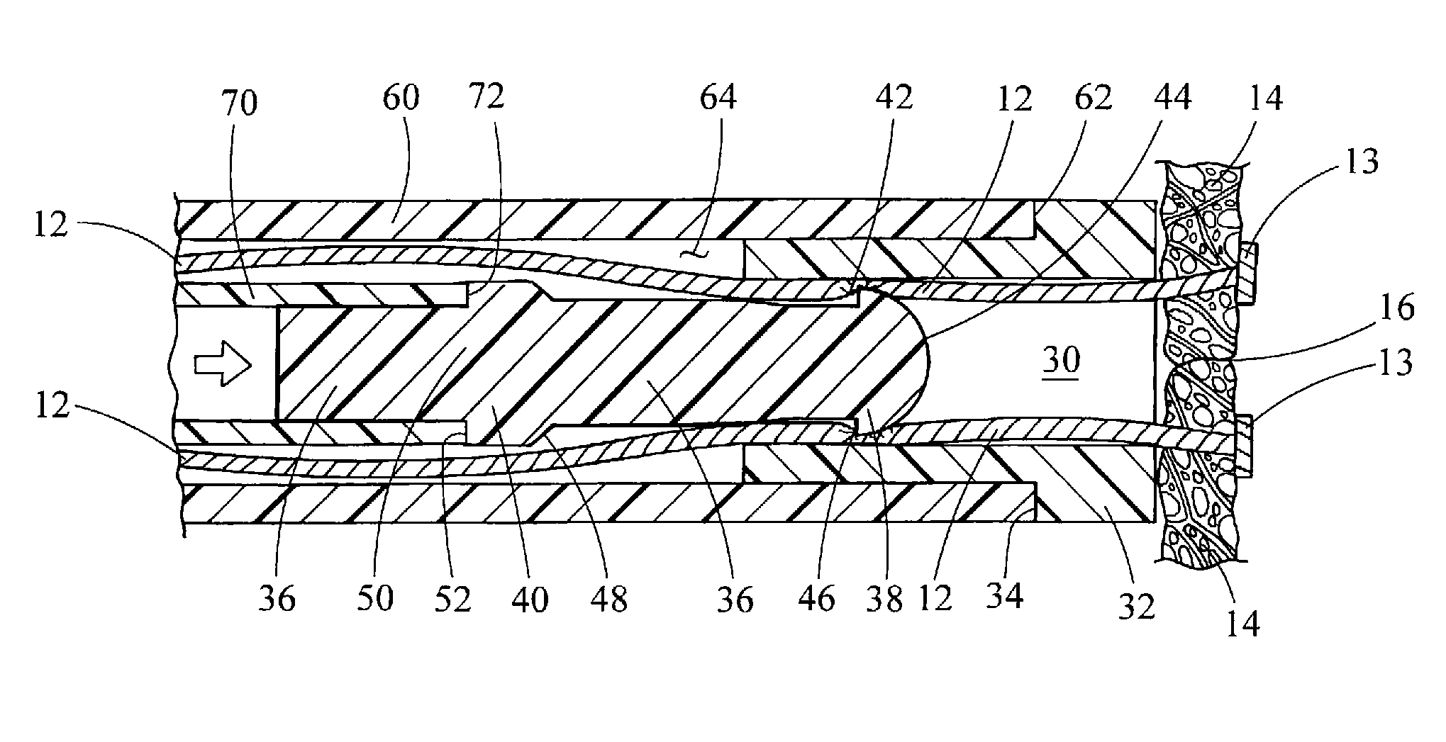
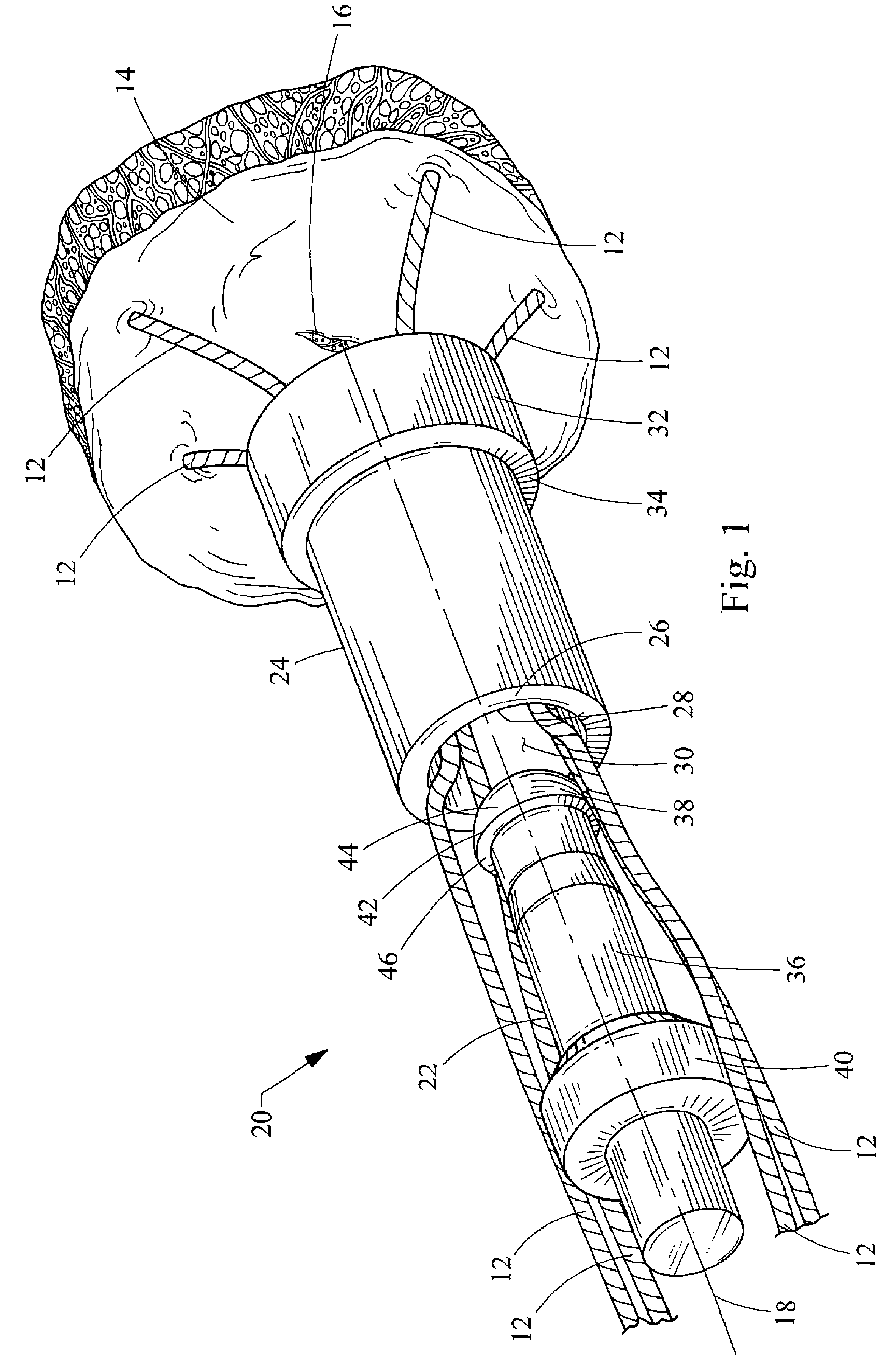
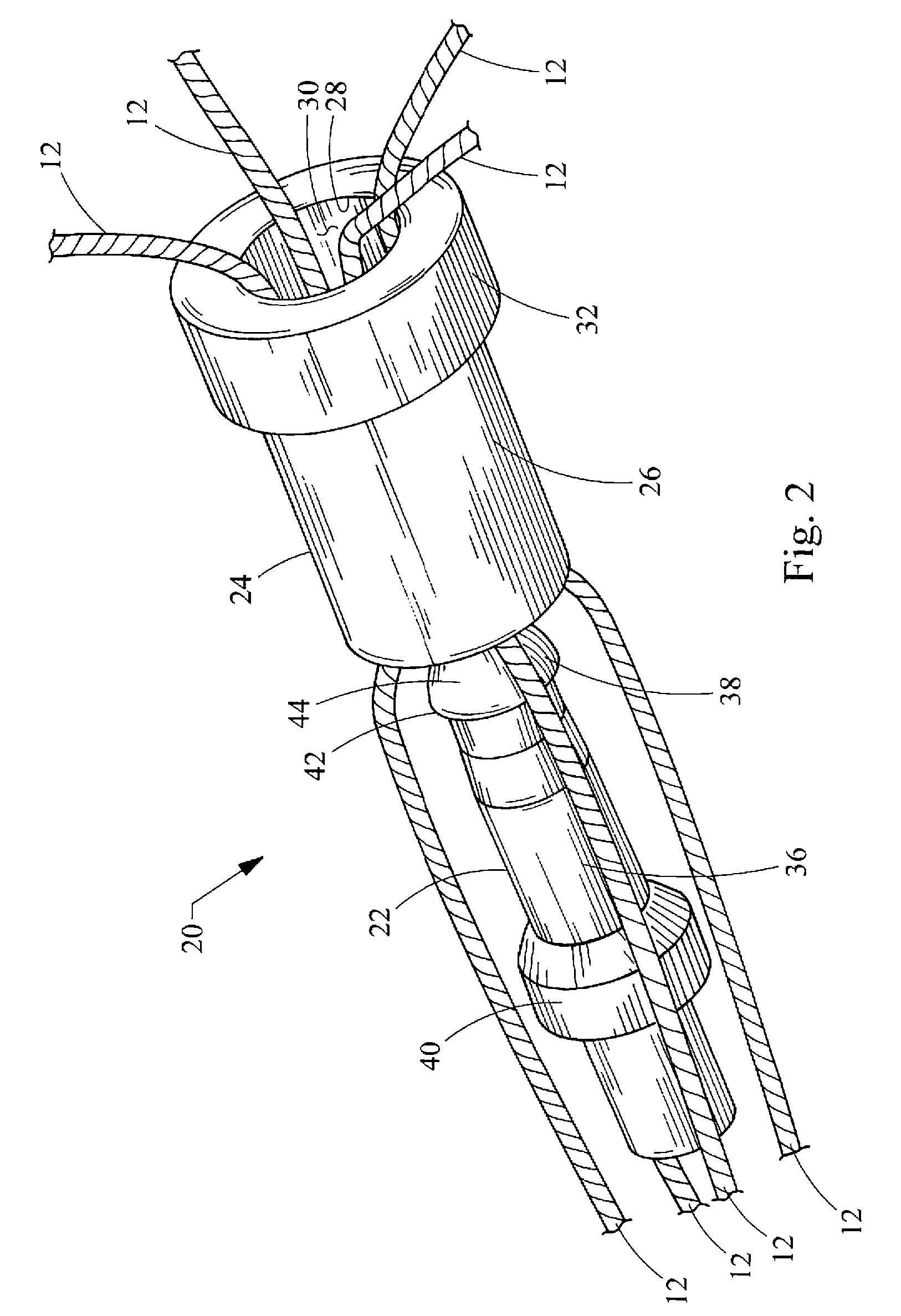
[0005]The present invention provides suture locks, as well as related systems and methods, for fixing strands of one or more sutures relative to tissue. The suture locks are simple and reliable in use, facilitate complete perforation closure and adjustment of the suture strands, and are adaptable to a variety of suture fixation and perforation closure situations. According to one embodiment of a suture lock constructed in accordance with the teachings of the present invention, the suture lock generally includes a locking pin and a retaining sleeve. The locking pin has a main body and a grip. The grip extends radially from the main body and defines an annular edge. The retaining sleeve has a tubular body within an internal wall defining an internal passageway sized to receive the locking pin therein. The suture lock is operable between a locked configuration and unlocked configuration. In the locked configuration, the suture strands are compressed between the grip and the internal wall of the tubular body.
[0006]According to more detailed aspects of the suture lock, the suture strands are compressed between the annular edge of the grip and the internal wall of the tubular body in the locked configuration. Preferably, the suture strands are also compressed between the main body and the internal wall of the tubular body in the locked configuration. The locking pin and retaining sleeve are connected in the locked configuration through their respective frictional engagement of the suture strands. In the locked configuration, the grip is structured to permit translation of the suture strands in a proximal direction (i.e. away from the tissue) and prevent translation of the suture strands in a distal direction (i.e. towards the tissue). The grip is preferably formed at a distal tip of the locking pin, and most preferably is dome-shaped.
[0008]According to more detailed aspects of the system, the first lumen of the first pushing catheter is sized to receive the second pushing catheter. Relative translation of the first pushing catheter and the second pushing catheter controls the relative positions of the retaining sleeve and the locking pin to operate the suture lock between a locked configuration and an unlocked configuration. The stop of the locking pin is sized to abut against the tubular body of the retaining sleeve to limit the relative positions of the locking pin and the retaining sleeve. The stop is also positioned relative to the grip to prevent the grip from passing completely through the internal passageway of the retaining sleeve. The suture strands pass through the second lumen of the second pushing catheter to a location outside of the body for manipulation thereof.
[0010]According to more detailed aspects of the method, the suture strands may be pulled in the proximal direction while pushing the second pushing catheter and the locking pin distally. The second pushing catheter and the locking pin are pushed distally relative to the first pushing catheter and retaining sleeve. The method may further include the steps of adjusting the tension on the suture strands. Preferably, the one or more sutures are placed around a perforation in the tissue, and the suture strands are placed in sufficient tension to close the perforation. The tension on the suture strands is maintained while the second pushing catheter and locking pin are pushed distally relative to the first pushing catheter and retaining sleeve. The frictional engagement of the locking pin with the suture strands, and of the retaining sleeve with the suture strands, is reinforced by the tension of the suture strands and the natural elasticity of the tissue.

Problems solved by technology

Manually tying sutures strands together to close a perforation can be very complex and time consuming.
For example, a significant level of skill and coordination is required by the medical professional, especially when the perforation and sutures are difficult to access within the body, such as in endoscopic or laparoscopic procedures.
The numerous difficulties with manually tying sutures are well documented.
Unfortunately, such automatic systems are often complex and costly, difficult to use, and limited to use in certain situations.

Method used


Image

  • Suture lock
  • Suture lock
  • Suture lock

Examples


Embodiment Construction

[0018]Turning now to the figures, FIGS. 1-4 depict one embodiment of a suture lock 20 and its components, constructed in accordance with the teachings of the present invention. The suture lock 20 generally comprises a locking pin 22 and a retaining sleeve 24 which are used to fix the strands 12 of one or more sutures relative to bodily tissue 14, such as for closing a perforation 16 in the tissue 14. Preferably, the suture is formed of nylon 2-0 and of the monofilament variety, although any suture material or construction may be used with the suture lock 20 of the present invention. Generally, the suture strands 12 will be placed through the tissue 14 and connected thereto using standard suturing techniques or devices such as T-anchors, staples or the like, leaving the strands 12 on one side of the tissue 14 for tying them together. Although the retaining sleeve 24 and locking pin 22 have been depicted as having circular cross-sections, it will be recognized that other cross-section...


PUM


Abstract

Suture locks, as well as related systems and methods, are provided for fixing strands of one or more sutures relative to tissue. The suture locks, systems and methods are simple and reliable in use, facilitate complete perforation closure and adjustment of the suture strands, and are adaptable to a variety of suture fixation and perforation closure situations. The suture lock includes a locking pin and a retaining sleeve. The locking pin has a main body and a grip. The retaining sleeve has a tubular body with an internal wall defining an internal passageway sized to receive the locking pin therein. The suture lock is operable between a locked configuration and unlocked configuration. In the locked configuration, the suture strands are compressed between the grip and the internal wall of the tubular body.

Description

CROSS-REFERENCE TO RELATED APPLICATIONS[0001]This application claims the benefit of U.S. Provisional Application Ser. No. 60 / 941,086 filed on May 31, 2007, entitled “SUTURE LOCK,” the entire contents of which are incorporated herein by reference.FIELD OF THE INVENTION[0002]The present invention relates generally to suture locks for fixing the strands of one or more sutures relative to bodily tissue, such as for closing perforations in the tissue.BACKGROUND OF THE INVENTION[0003]Perforations in the walls of internal organs and vessels may be naturally occurring, or formed intentionally or unintentionally. In order to permanently close these perforations and allow the tissue to properly heal, numerous medical devices and methods have been developed employing sutures, adhesives, clips, staples, anchors and the like. Many of these devices typically employ one or more sutures, the strands of which must be brought together and fixed in place in order to close the perforation.[0004]Manuall...

Claims


Application Information

Patent Timeline
Patent Type & Authority Patents(United States)
IPC IPC(8): A61B17/04
CPCA61B2017/0488A61B17/0487A61B17/0401A61B2017/0414
Inventor SURTI, VIHAR, C.
Owner COOK MEDICAL TECH LLC
Learn More