Connectored cable and method for manufacturing connectored cable
a technology of connectors and connectors, which is applied in the direction of optics, instruments, optical elements, etc., can solve the problems of foreign matter deposited on the optical connectors and degrade signals, and achieve the effect of reducing the likelihood of moving within the connector and suppressing the damage to the optical coupling portion
- Summary
- Abstract
- Description
- Claims
- Application Information
AI Technical Summary
Benefits of technology
Problems solved by technology
Method used
Image

Examples
modified examples
First Modified Example
Example in Which Number of Loops of Optical Fiber 3 is Changed
[0214]In the foregoing embodiment, the extra length of the optical fiber 3 is managed by approximately two loops within the connector, and there were three bent portions within the connector. However, a method for managing the extra length of the optical fiber 3 within the connector is not limited to this. The extra length of the optical fiber 3 may also be managed by three or more loops within the connector.
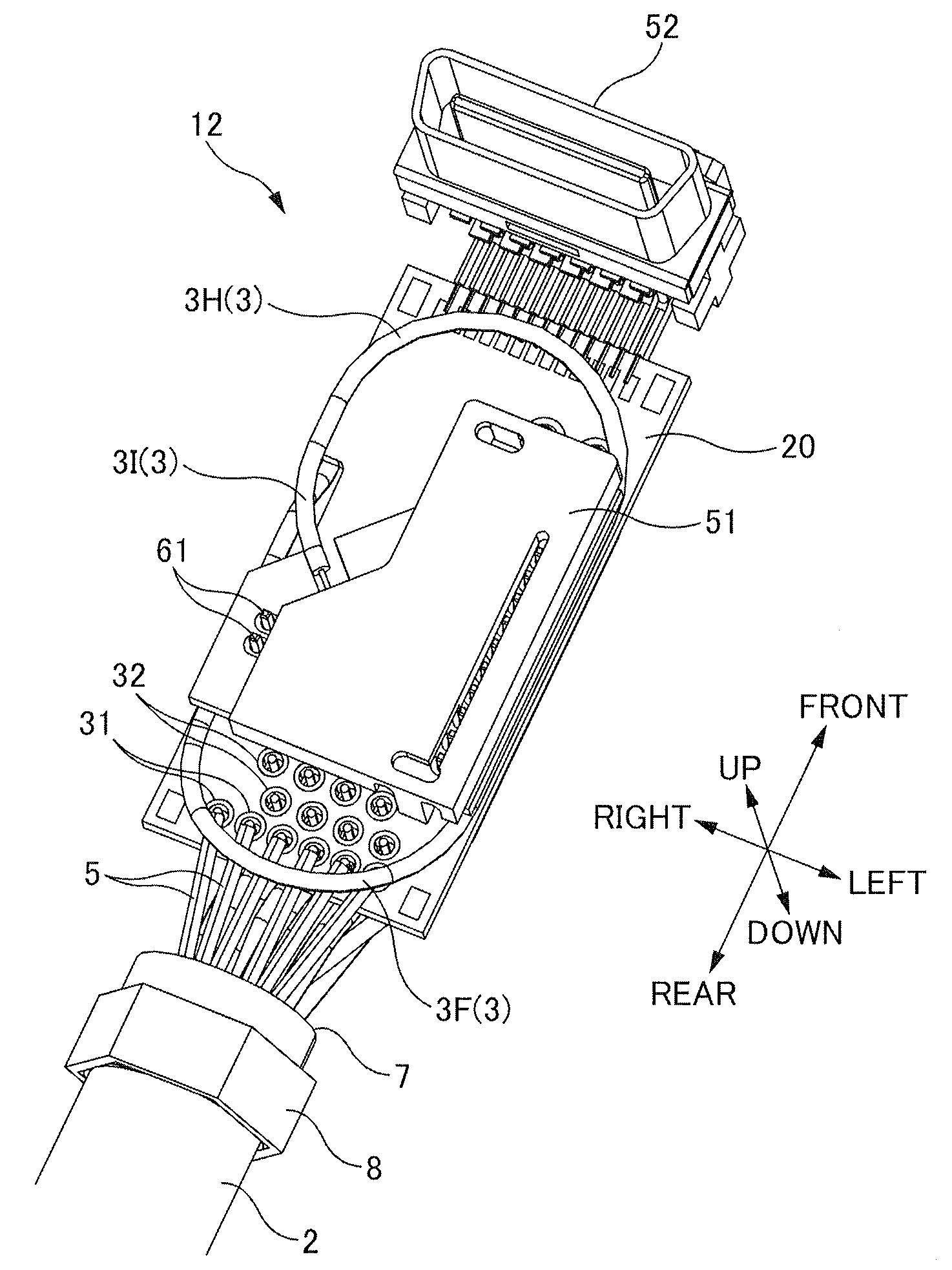
[0215]FIG. 20 is a perspective view of the termination portion 12 of the camera-side connector 10 according to the first modified example as seen obliquely from below. It should be noted that the configuration and wiring on the upper side of the parent substrate 20 are the same as those of the above-described embodiment and therefore are omitted from the drawing.
[0216]In the first modified example, the extra length of the optical fiber 3 is managed by approximately three loops within the housing ...
second modified example
Example in Which Parent Substrate and Child Substrate are Not Separated
[0221]In the above-described embodiment, the parent substrate and the child substrate are separated from each other, which facilitates the connecting operation and the wiring operation of the optical fiber 3, the signal lines 5, and the power supply lines 6. However, if it is allowable to take time and effort for the connecting operation and the wiring operation, it is not necessary to separate the parent substrate and the child substrate from each other. In the case where the parent substrate and the child substrate are not separated from each other, the photoelectric conversion portion (the light-emitting portion 41 or the light-receiving portion 141) is installed on the parent substrate 20 by directly mounting it on the parent substrate 20.
[0222]FIG. 21 is a perspective view of the termination portion 12 of the camera-side connector 10 according to the second modified example as seen obliquely from above. As s...
third modified example
Example in Which Parent Substrate Does Not Have Recess
[0227]In the above-described embodiment, the parent substrate has the recess formed thereon, and the optical fiber 3 is wired from the lower side to the upper side of the parent substrate through the recess. However, the parent substrate may not have the recess.
[0228]FIG. 22 shows the termination portion 112 of the grabber-side connector 110 according to the third modified example as seen obliquely from above. As shown in this drawing, in the third modified example, the recess 124 is not formed on the right edge of the parent substrate 120. Moreover, in the third modified example, the optical fiber 3 is wired from the lower side to the upper side, passing the outer side of the right edge of the parent substrate 120.
[0229]In the third modified example, it is necessary to provide a space that is approximately equal to the diameter of the optical fiber between the inner surface of the housing 111 and the right edge of the parent sub...
PUM
| Property | Measurement | Unit |
|---|---|---|
| transmission distance | aaaaa | aaaaa |
| transmission distance | aaaaa | aaaaa |
| outer diameter | aaaaa | aaaaa |
Abstract
Description
Claims
Application Information
 - R&D
- Intellectual Property
- Life Sciences
- Materials
- Tech Scout
- Unparalleled Data Quality
- Higher Quality Content
- 60% Fewer Hallucinations
Browse by: Latest US Patents, China's latest patents, Technical Efficacy Thesaurus, Application Domain, Technology Topic, Popular Technical Reports.
© 2025 PatSnap. All rights reserved.Legal|Privacy policy|Modern Slavery Act Transparency Statement|Sitemap|About US| Contact US: help@patsnap.com