
System and method for controlling operation of a component on a computer system

a computer system and component technology, applied in the direction of data conversion, instruments, input/output to record carriers, etc., can solve the problems of complex and lack of versatility, laborious and time-consuming process of generating hardware identification, and the use of software applications and computer programs, so as to achieve convenient use

Active Publication Date: 2014-05-27
FLEXERA SOFTWARE
View PDF9 Cites 0 Cited by
  • Summary
  • Abstract
  • Description
  • Claims
  • Application Information

AI Technical Summary

Benefits of technology

The present invention is a system and method for controlling the operation of a component in a computer system. It solves the problems of prior art by being versatile and easy to use. It can quickly calculate a control identity to determine whether a component can be operated in a particular computer system, and can adapt to changes in hardware and software applications within the system. This results in a flexible system that ensures efficient and effective component operation.

Problems solved by technology

However, occasions of illegal use of software applications and computer programs are common, and there exists a significant problem over monitoring the authorized use of a software application or computer program in a computer system, particularly in a computer system in which the software applications and / or hardware devices are subject to change over time.
Such a known system has a number of disadvantages, including particularly complexity and lack of versatility.
For example, the need to check and identify each and every hardware device within each class of hardware device in the computer system in order to establish the hardware identification renders the process of generating the hardware identification laborious and time consuming.
Furthermore, the known system monitors only the hardware within the computer system and takes no account of the software, and this is an inherent limitation.

Method used

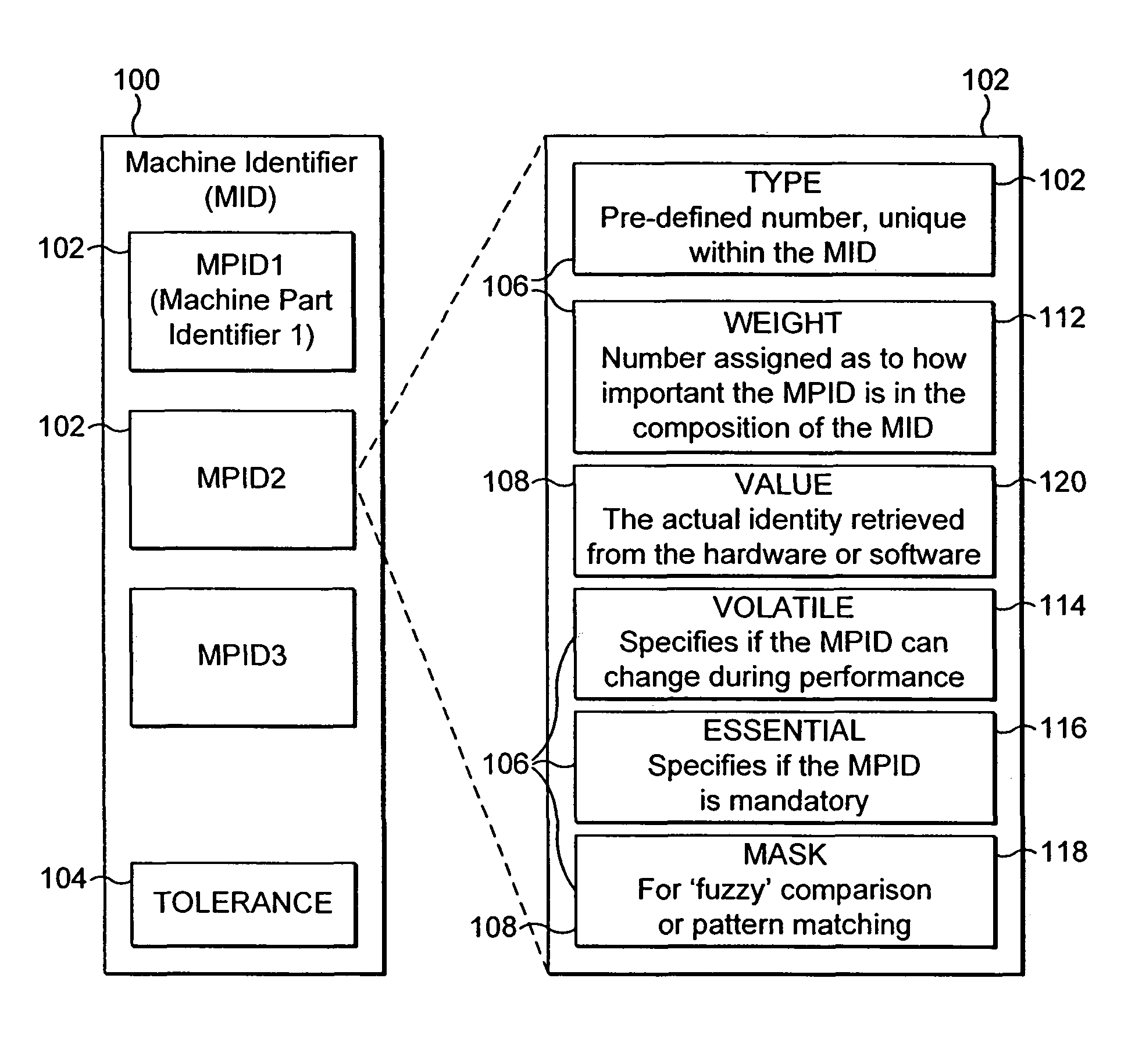
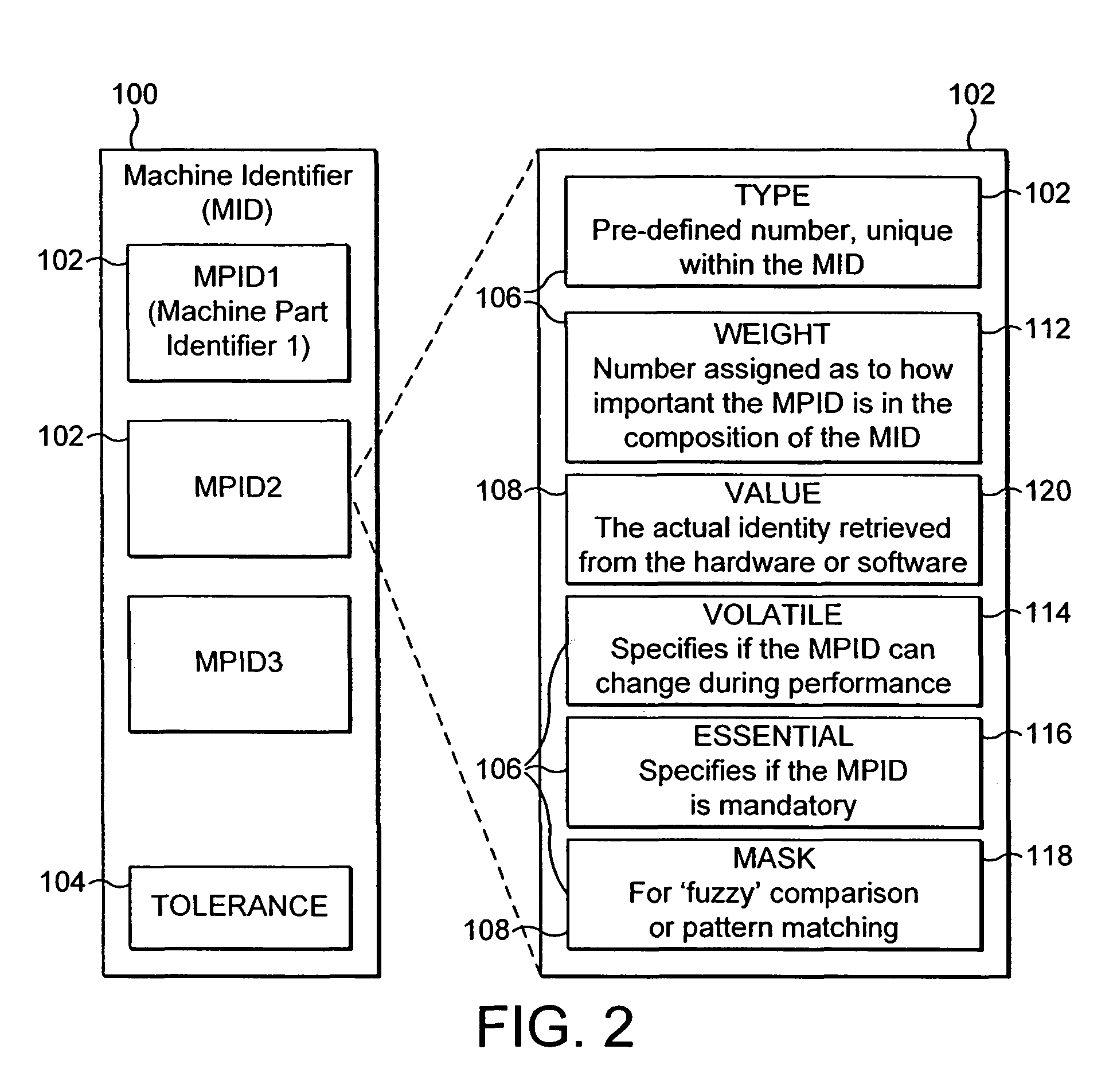

Image

  • System and method for controlling operation of a component on a computer system
  • System and method for controlling operation of a component on a computer system
  • System and method for controlling operation of a component on a computer system

Examples


Embodiment Construction

[0039]The invention will now be described with reference to an embodiment shown in the drawings. It is to be understood that the described embodiment is illustrative only, and that various modifications are possible, some of which will be mentioned in the following description.

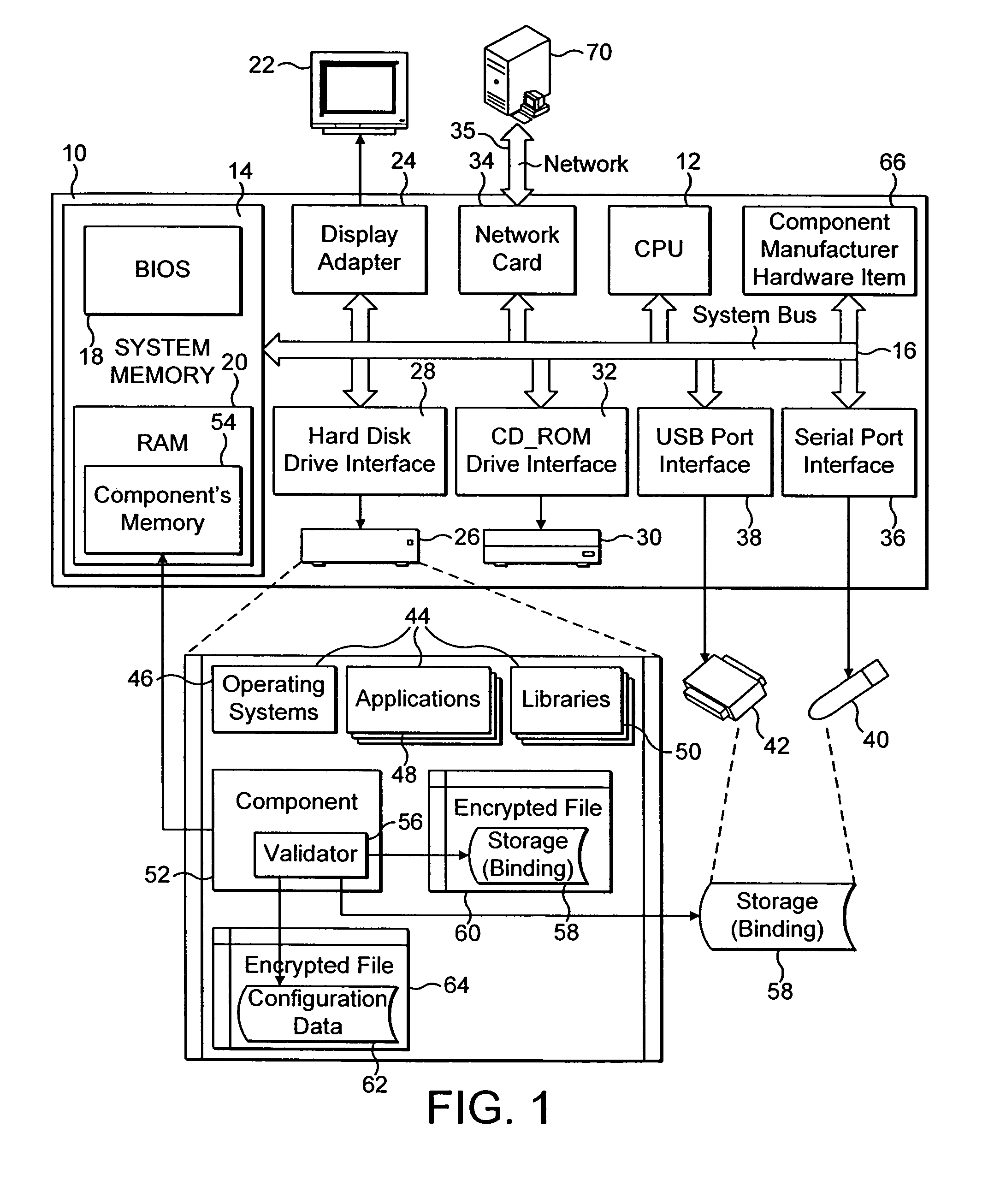
[0040]Referring initially to FIG. 1, a computer system embodying the present invention comprises a computer 10 typically including a central processing unit (CPU) 12, a system memory 14 and a system bus 16 for coupling the various devices of the computer 10, including the system memory 14, to the CPU 12. The system memory may include a basic input / output system (BIOS) 18 containing the basic routines for transferring information between elements within the computer 10, and a random access memory (RAM) 20.

[0041]In addition, the computer system of FIG. 1 includes a display 22 connected to the system bus 16 by way of a display adaptor 24. It is assumed in the present description that the computer system is in the...


PUM


Abstract

The present invention provides a system and method for generating a control identity for binding together a component and a computer system including hardware devices and software applications. The binding system comprises a processor, a validator module for controlling the processor to generate the control identity, and a store for storing the control identity. The validator module is arranged to define a binding configuration for the component, representing a weighted combination of at least one of a set of hardware elements and a set of software elements needed within the computer system for operation of the component, the validator module also being arranged to prompt the processor to establish whether instances of the elements within the at least one set of elements are present in the computer system. The validator module assigns to each category of element that is established to be present an identity value and adds the identity value to data representing the binding configuration to define the control identity. The validator module then causes the control identity to be transferred to the store.

Description

FIELD OF THE INVENTION[0001]The present invention relates to a system and a method for controlling the operation of a component in a computer system. In particular, the invention relates to a system and a method for controlling authorization of a component to operate in a computer system having tolerance for changes. The component may be a software component or a hardware component.BACKGROUND OF THE INVENTION[0002]The use of a given software application or computer program in a computer system is generally managed under license, with the license allocating particular rights of use to a specific computer system. However, occasions of illegal use of software applications and computer programs are common, and there exists a significant problem over monitoring the authorized use of a software application or computer program in a computer system, particularly in a computer system in which the software applications and / or hardware devices are subject to change over time.[0003]EP-1469369 d...

Claims


Application Information

Patent Timeline
Patent Type & Authority Patents(United States)
IPC IPC(8): G06F3/00G06F3/06G06F21/12
CPCG06F2221/0704G06F21/51G06F2221/2129G06F21/73G06F21/10G06F21/57G06F2221/2107G06F3/0689G06F21/6272G06F2221/2101G06F21/1011G06F15/177
Inventor UWAIS, MOHAMED, SHAMIL
Owner FLEXERA SOFTWARE
Learn More