
Elevator grip assurance

a technology for ensuring the grip of the elevator, applied in the direction of transportation and packaging, drilling pipes, wellbore/well accessories, etc., can solve the problem of not providing the interlocking system

Active Publication Date: 2014-05-27
FRANKS INT
View PDF36 Cites 15 Cited by
  • Summary
  • Abstract
  • Description
  • Claims
  • Application Information

AI Technical Summary

Benefits of technology

The invention is about a device that prevents a load from moving in a tubular support system. It includes a member and a sensor to detect movement. When the load is detected, the device locks the system in a closed position to prevent the load from moving. This ensures the safety of the elevator and the load.

Problems solved by technology

However, heretofore an interlock system has not been provided that prevents opening a tubular support device in response to sensing a load acting on the tubular support device.

Method used


Image

  • Elevator grip assurance
  • Elevator grip assurance
  • Elevator grip assurance

Examples


Embodiment Construction

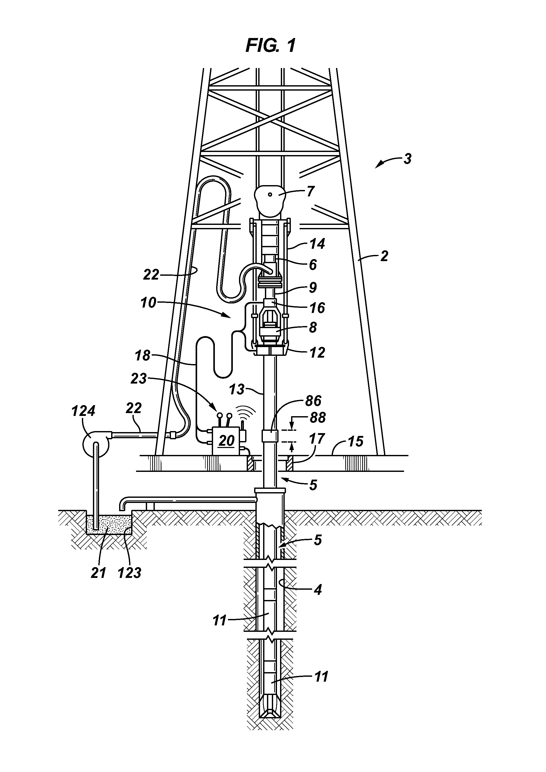
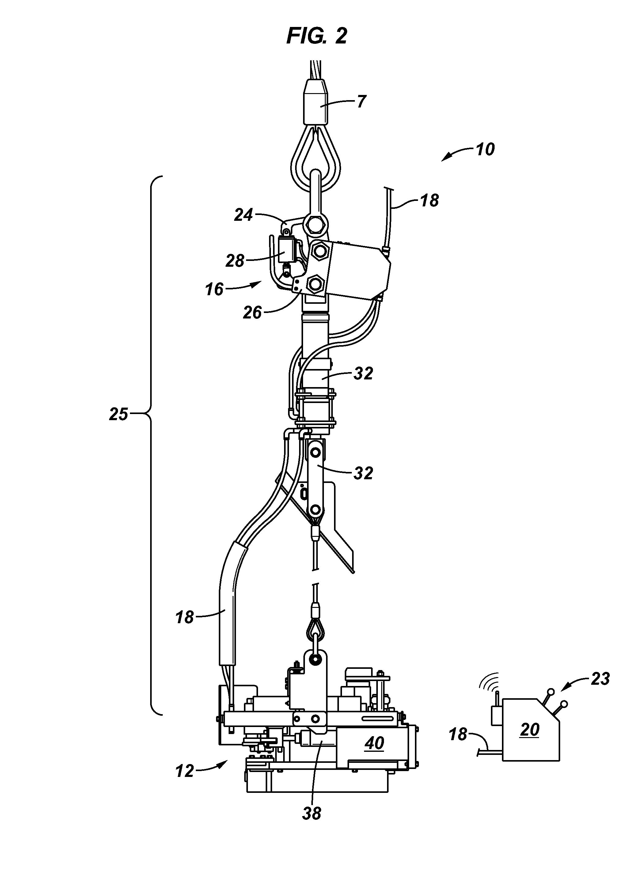
[0019]It is to be understood that the following disclosure provides many different embodiments, or examples, for implementing different features of various embodiments. Specific examples of components and arrangements are described below to simplify the present disclosure. These are, of course, merely examples and are not intended to be limiting. In addition, the present disclosure may repeat reference numerals and / or letters in the various examples. This repetition is for the purpose of simplicity and clarity and does not in itself dictate a relationship between the various embodiments and / or configurations discussed. Moreover, the formation of a first feature over or on a second feature in the description that follows may include embodiments in which the first and second features are formed in direct contact, and may also include embodiments in which additional features may be formed interposing the first and second features, such that the first and second features may not be in d...


PUM


Abstract

According to one or more aspects of the invention an interlock device is adapted for connection within a load path of a tubular support device to lock the tubular support device in a closed position in response to detecting a load suspended from the tubular support device. The interlock device includes a first member moveably connected to a second member and a biasing mechanism operationally connected to the first member and the second member providing a load setting resisting movement of the first member and the second member relative to one another. The first and the second member may be rotationally locked with one another to transmit rotation across the interlock device to the elevator.

Description

RELATED APPLICATIONS[0001]This application is a non-provisional application claiming priority to provisional application No. 61 / 309,202, filed on Mar. 1, 2010, which is hereby incorporated by reference in its entirety.BACKGROUND[0002]This section provides background information to facilitate a better understanding of the various aspects of the present invention. It should be understood that the statements in this section of this document are to be read in this light, and not as admissions of prior art.[0003]Tubular strings are inserted into and pulled from wellbores (e.g., boreholes) at various times during the life of a well for various purposes. For example, tubular strings (e.g., drill pipe) are assembled and run into the well for drilling the wellbore, to line the wellbore (e.g., casing, liners, screens, etc.), and to position tools (e.g., tubing, etc.) in the wellbore.[0004]A rig is typically employed to assemble the tubular string for insertion into the wellbore and to dissemb...

Claims


Application Information

Patent Timeline
IPC IPC(8): E21B19/16
CPCE21B44/00E21B19/07E21B19/16E21B40/00E21B41/0021E21B19/165E21B19/06
Inventor BOULIGNY, VERNONTHERIOT, PHILLIP M.COMEAUX, REESE
Owner FRANKS INT
Learn More