
Medical emergency crash cart

a technology of auxiliary swivel caster and caster, which is applied in the directions of transportation and packaging, surgery, diagnostics, etc., can solve the problems of high speed travel, medical equipment, instruments, and supplies are expensive, and hospitals may maintain only a limited number of crash carts, so as to improve maneuverability and stability, and the effect of high maneuverability

Active Publication Date: 2014-04-15
INTERMETRO IND CORP
View PDF11 Cites 3 Cited by
  • Summary
  • Abstract
  • Description
  • Claims
  • Application Information

AI Technical Summary

Benefits of technology

The present invention is a cart that is easy to move and has a space to store items. It can be used with different types of wheeled devices, such as stretchers, medical storage carts, and hospital beds, as well as other utility carts. However, it is not limited to medical carts and can be used with any device that needs better maneuverability and stability.

Problems solved by technology

One drawback of many known crash carts is a lack of stability during high speed travel.
Second, as medical equipment, instruments, and supplies are expensive, hospitals may maintain only a limited number of crash carts (e.g. one crash cart per floor or station).
Therefore, when a medical emergency occurs, a crash cart operator must rush the cart through the hospital corridors often over relatively long distances to a patient.
However, the swivel casters may cause the cart to be difficult to steer at high speeds particularly when an attempt is made to change the direction of movement, for example, by going around corners in corridors or turning into a patient's room.
Therefore, the crash cart operator must either reduce his speed through the corridors or risk overturning the cart.
The risk of overturning increases when the operator must negotiate the cart around a corner, as swivel casters do not provide a firm pivot about which to turn but rather permit inertia of the cart to cause it to tend to continue to move in its original direction.
However, this is less efficient and may, in fact, not be possible during a given emergency.
However, while the mechanisms disclosed in these patents have many advantages, they are not well suited for dynamic actuation while a cart is in motion.
For example, actuators for these mechanisms may be located on a side of a cart and / or may be positioned for actuation by an operator's foot, or may be otherwise inconvenient for the operator to actuate while the cart is in motion.
However, the fifth wheel cannot be raised and lowered quickly.
Accordingly, the fifth wheel disclosed in the Levine Patent is not well-suited for use in emergency situations.
For these and other reasons, the crash carts and related mechanisms for improving mobility of wheeled apparatuses of the prior art are not entirely satisfactory.

Method used


Image

  • Medical emergency crash cart
  • Medical emergency crash cart
  • Medical emergency crash cart

Examples


first embodiment

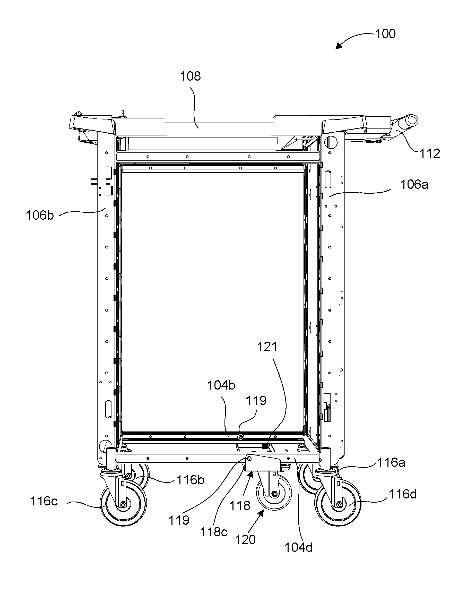
[0044]An embodiment of the caster direction-locking mechanism 122 of the present invention is described with reference to FIGS. 7 through 19. A mounting plate 140 is provided to attach the caster direction-locking mechanism 122 to the auxiliary wheel support member 118. The mounting plate 140 includes three apertures 140a, 140b, and 140c formed therein, as shown in FIG. 11. A threaded end of a bolt (not labeled) is inserted into each of the apertures 140a and 140b, and through corresponding apertures (not shown) formed in the auxiliary wheel support member 118. A nut (not labeled) is securely attached to the threaded end of each of the bolts, thereby securing the mounting plate 140 to the auxiliary wheel support member 118.

[0045]The caster direction-locking mechanism 122 is pivotally attached to the mounting plate 140 using a shoulder screw 146 and a nut 148. More particularly, as best shown FIG. 11, a threaded end of the shoulder screw 146 is inserted through an aperture of a first...

second embodiment

[0069]FIG. 21 illustrates a top view of a second embodiment of an auxiliary swivel caster wheel assembly 1120 of the present invention. The swivel caster wheel assembly 1120 operates in a similar fashion to the caster direction-locking mechanism 120 described above. The swivel caster wheel assembly 1120 includes a horn 1128 having a top portion 1128a that has a notch 1128d formed therethrough. The notch 1128d of the swivel caster wheel assembly 1120 shown in FIG. 21 is deeper and wider than the notch 128d of the swivel caster wheel assembly 120 shown in FIG. 6. The shape of the notch 1128d enables the outer portion 1172a of the bearing assembly 1172 to engage the notch 1128d, when the trigger mechanism 114 is actuated.

[0070]As described above, the outer portion 1172a of the bearing assembly 1172 is enabled to rotate freely about the second shoulder screw 1146b. When the trigger mechanism 114 is actuated, the swivel lock bracket 1144 is urged toward the auxiliary swivel caster wheel ...


PUM


Abstract

A utility cart includes an auxiliary swivel caster wheel assembly, a locking mechanism, and a trigger mechanism for causing the locking mechanism to releasably lock the auxiliary swivel caster wheel assembly. The auxiliary swivel caster wheel assembly is unlocked to enable the auxiliary swivel caster wheel to rotate about a vertical axis for improved maneuverability in small areas, and is locked to hold the auxiliary swivel caster wheel in a predetermined position for improved steering as the cart is moved from one location to another. The trigger mechanism is disposed on a steering handle to enable dynamic actuation of the locking mechanism while the cart is in motion.

Description

BACKGROUND OF THE INVENTION[0001]1. Field of the Invention[0002]The present invention relates to an auxiliary swivel caster wheel assembly and a caster direction-locking mechanism for a mobile utility cart, and more particularly to such a wheel assembly and locking mechanism for a mobile utility cart commonly called a “medical emergency crash cart” or simply a “crash cart”, for medical emergency use in hospitals and other medical institutions. The auxiliary swivel caster wheel assembly and direction-locking caster mechanism in accordance with the present invention provide the crash cart with improved high speed stability and maneuverability. A trigger mechanism for selectively locking and unlocking the direction-locking caster mechanism also is included.[0003]2. Description of Related Art[0004]A medical emergency crash cart commonly contains medical equipment, instruments, and supplies that may be required while responding to medical emergencies, particularly for medical procedures ...

Claims


Application Information

Patent Timeline
Patent Type & Authority Patents(United States)
IPC IPC(8): B62B5/04B62B3/00
CPCB60B33/025A61B2019/025B60B33/0068A61B19/0248B60B33/0073B60B33/026B60B33/0007B60B33/0049B60B33/0018B60B33/0057B60B33/0039A61B50/10A61B50/13B62B3/008B60B2200/43B62B3/001B62B2301/00B60B9/005B60B27/0005B60B27/06
Inventor JANICK, JAMES J.WELCH, ROBERT J.STEELE, ROBERT R.SINHA, SANJEEB
Owner INTERMETRO IND CORP
Learn More