
Nail guiding structure and nail gun comprising the same

a technology of guiding structure and nail gun, which is applied in the direction of nailing tools, packaging, stapling tools, etc., can solve the problems of nail gun slipping, nail slipping, nail slipping,

Active Publication Date: 2014-04-15
APEX MFG
View PDF13 Cites 10 Cited by
  • Summary
  • Abstract
  • Description
  • Claims
  • Application Information

AI Technical Summary

Benefits of technology

The supporting member in this patent can hold nails upright while being punched out by a nail gun. It can be slid back to different positions before the nails hit it, making sure the nails are punched properly and not crooked or stuck. This allows the supporting member to be used with different thicknesses of nails, ensuring accuracy and consistency in the punching process.

Problems solved by technology

However, the nail guiding structure of said patent is only available for one thickness of nails.
If a user loads thinner nails into the nail gun, two nails might be disposed in front of the nail rail, so that its punching board will punch two nails in the same time, and the nails will be crooked, deformed or even stuck in the nail gun.

Method used


Image

  • Nail guiding structure and nail gun comprising the same
  • Nail guiding structure and nail gun comprising the same
  • Nail guiding structure and nail gun comprising the same

Examples


Embodiment Construction

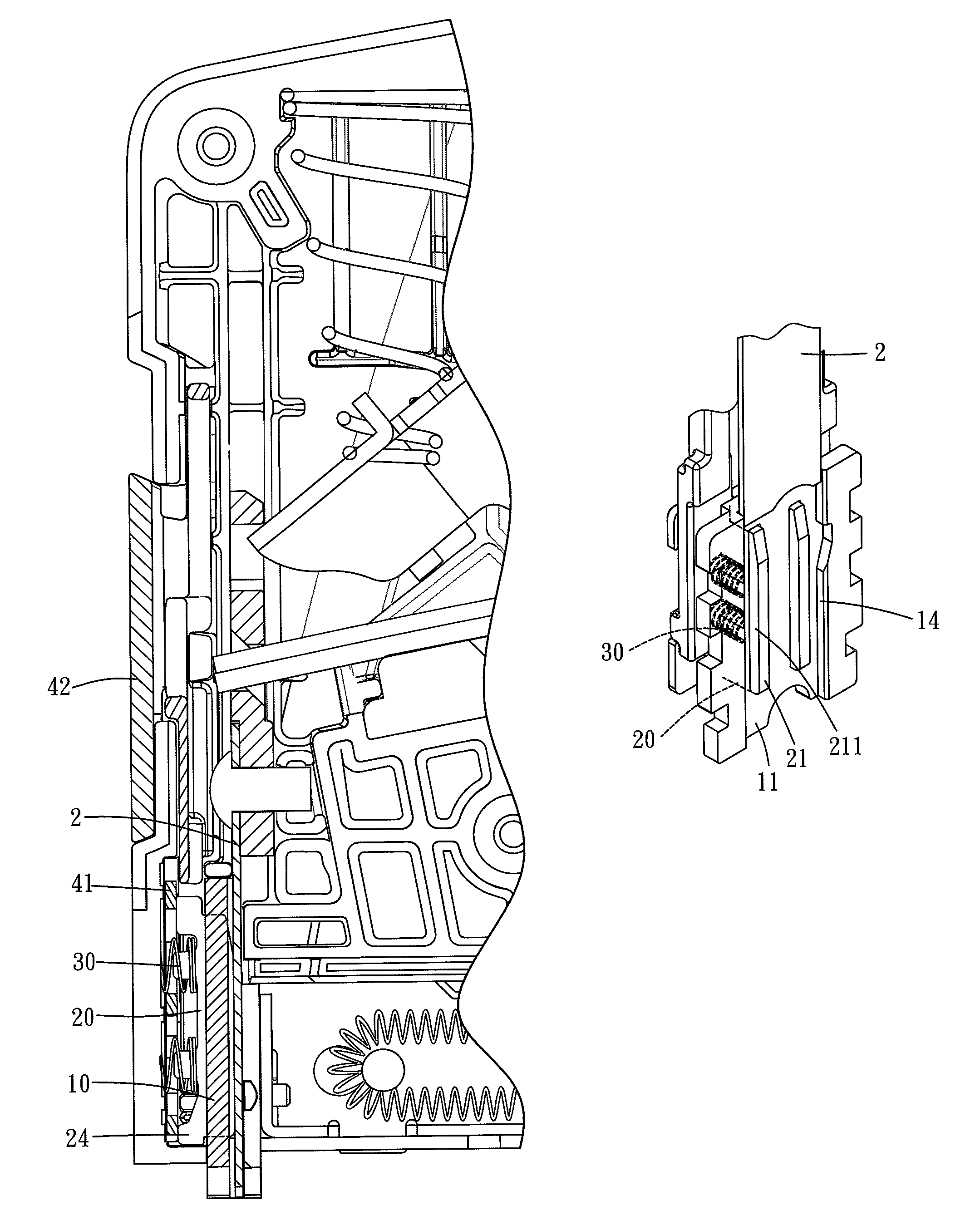
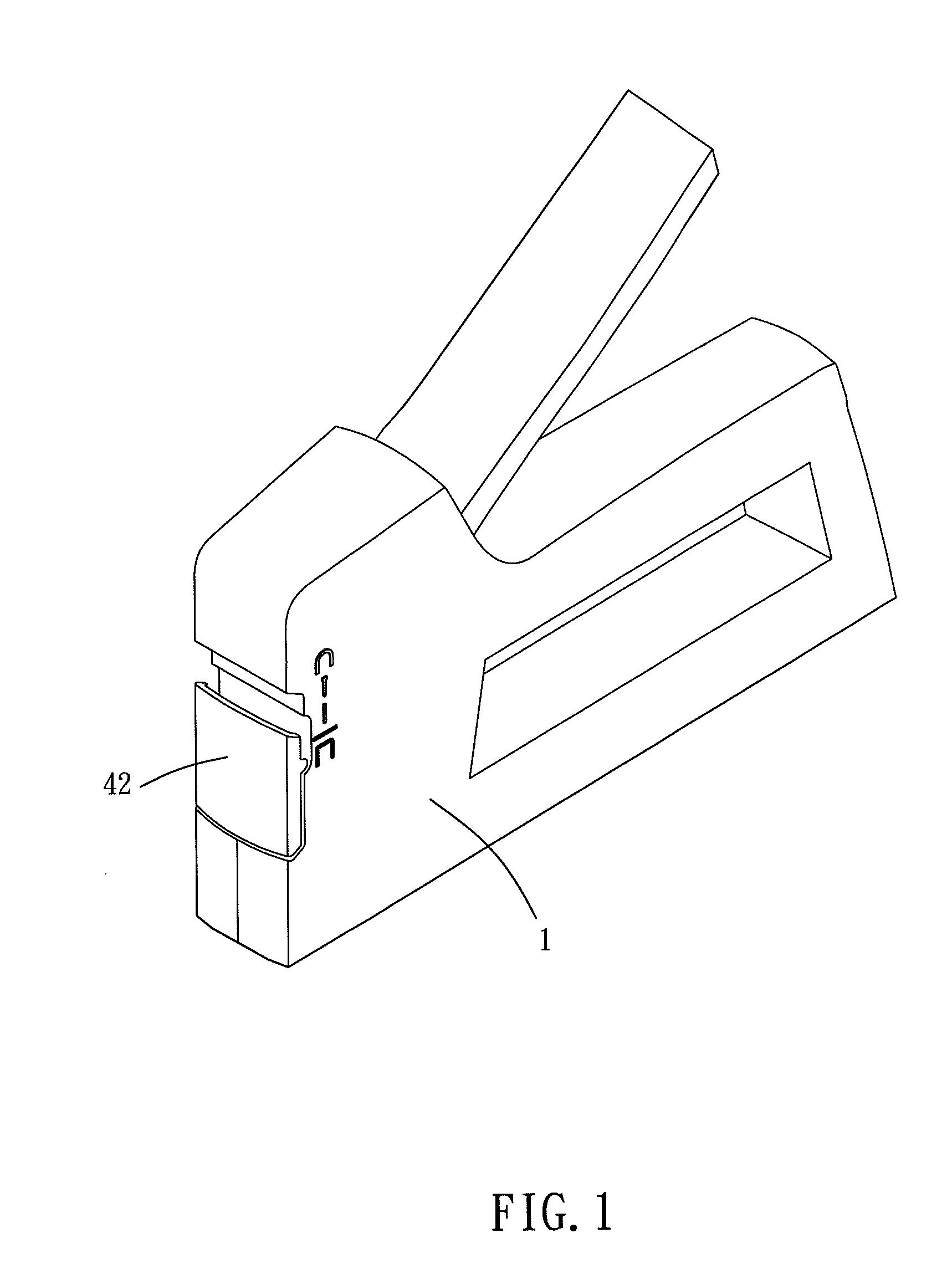
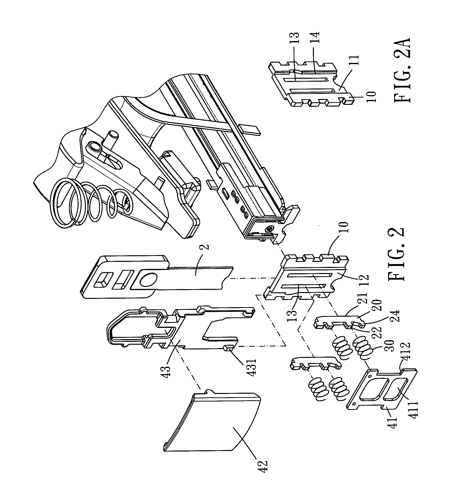
[0021]Please refer to FIGS. 1 to 4, the present invention provides a nail guiding structure for being disposed inside of a nail gun which has a nail rail. The nail guiding structure is adapted to be disposed in front of the nail rail. The nail guiding structure includes a guiding panel 10, at least one supporting member 20, at least one pushing means, and at least one holding means.

[0022]The guiding panel 10 is vertically disposed in front of the nail rail, and the guiding panel 10 has a first surface 11 and a second surface 12 opposite to the first surface 11. The first surface 11 faces the nail rail, and the guiding panel 10 is formed with at least one positioning slot 13 (there are two positioning slots in this embodiment). The positioning slot 13 passes through the first surface 11 and the second surface 12 of the guiding panel 10. Preferably, the first surface 11 of the guiding panel is formed with a guiding groove 14 which extends vertically. The guiding groove 14 is adapted t...


PUM

PropertyMeasurementUnit
guiding structureaaaaaaaaaa
flexibleaaaaaaaaaa
thicknessaaaaaaaaaa

Abstract

A nail guiding structure of the present invention is disposed inside of the nail gun having a nail rail. The nail guiding structure includes one or more supporting members and a holding mechanism. The supporting member can move between a first and a second position, wherein the supporting member can move toward the first position to elastically push nails in the air gun, so that the nails can be vertically held in front of the nail rail. The holding mechanism can selectively hold the supporting member, so that the supporting cannot move back to the second position. Thereby, a user can move the holding mechanism to adapt for different thicknesses of nails. Only one nail can move to the front of the nail rail every time when a punching board of the nail gun punches. Consequently, the problems of nail jamming or crookedly stapling are prevented.

Description

BACKGROUND OF THE INVENTION[0001]1. Field of the Invention[0002]The present invention relates to a nail guiding structure and a nail gun having the nail guiding structure.[0003]2. Description of the Prior Art[0004]A nail gun projects out nails with its punching board. And a nail guiding structure may be disposed in front of a nail rail of the nail gun so as to hold nails on the nail rail and avoid nails from being stuck in the nail gun.[0005]A nail guiding structure is disclosed in U.S. Pat. No. 5,692,665, wherein the FIG. 1 of said patent shows the extension parts 8, 9 can selectively pivot to the front of its nail rail and abut against nails so as to hold the nails. And its FIG. 3 further discloses that guiding parts 52, 62 are pivoted with a shaft 33, and the flexible base element 70 pushes the guiding parts 52, 62 to pivot toward the nail rail.[0006]However, the nail guiding structure of said patent is only available for one thickness of nails. If a user loads thinner nails into...

Claims


Application Information

Patent Timeline
Patent Type & Authority Patents(United States)
IPC IPC(8): B25C3/00
CPCB25C5/11B25C5/1665
Inventor WANG, JING-LIWANG, RONG-YU
Owner APEX MFG
Learn More