Blood pressure measurement device

a technology of measurement device and blood pressure, which is applied in the direction of catheters, instruments, angiography, etc., can solve the problems of increasing the number of components, increasing the unit price, and not lowering the reception performance of the standard radio wave, so as to achieve the effect of lowering the reception performan

Active Publication Date: 2014-04-01
OMRON HEALTHCARE CO LTD
View PDF6 Cites 0 Cited by
  • Summary
  • Abstract
  • Description
  • Claims
  • Application Information

AI Technical Summary

Benefits of technology

[0008]In the technique described in Patent Document 1, various considerations are made on the method of arranging an antenna and a plurality of motors, but consideration is not made on the method of arranging the antenna with respect to a metal surface. Therefore, if a directivity surface of the antenna is arranged parallel to the metal surface, the reception sensitivity may lower. In the technique described in Patent Document 2, directional characteristics improve if a configuration of adjusting the tilt of the antenna in the core axis direction is adopted, but the configuration becomes complicated and the number of components and the unit price increase.
[0009]Therefore, one or more embodiments of the present invention provides a blood pressure measurement device realizing a configuration of mounting the radio-controlled clock function in the main body of the blood pressure measurement device without lowering the reception performance of the standard radio wave of the radio-controlled clock.
[0011]According to one or more embodiments of the present invention, the pump is arranged such that an axis line direction of the motor and an extending direction of the magnetic body core are orthogonal, that is, the two directions intersect forming an angle of 90°, allowing the effect of not lowering the reception performance of the standard radio wave of the radio-controlled clock to be more efficiently obtained. However, the effect of not lowering the reception performance of the standard radio wave of the radio-controlled clock can be similarly obtained even if the angle formed by the axis line direction of the motor and the extending direction of the magnetic body core is not strictly 90° and is an angle slightly deviated from 90°. That is, “substantially orthogonal” includes a case where the axis line direction of the motor and the extending direction of the magnetic body core intersect forming the angle of 90° and also includes a case where the axis line direction of the motor and the extending direction of the magnetic body core intersect to form not 90° but an angle close to 90°. For example, according to one or more embodiments of the present invention, the axis line direction of the motor and the extending direction of the magnetic body core intersect to form an angle in a range of greater than or equal to 80° and smaller than or equal to 100°, or intersect to form an angle in a range of greater than or equal to 85° and smaller than or equal to 95°.
[0016]According to one or more embodiments of the present invention, the lowering of the reception performance of the standard radio wave of the radio-controlled clock mounted in the main body of the blood pressure measurement device can be suppressed.

Problems solved by technology

In the technique described in Patent Document 2, directional characteristics improve if a configuration of adjusting the tilt of the antenna in the core axis direction is adopted, but the configuration becomes complicated and the number of components and the unit price increase.
However, the effect of not lowering the reception performance of the standard radio wave of the radio-controlled clock can be similarly obtained even if the angle formed by the axis line direction of the motor and the extending direction of the magnetic body core is not strictly 90° and is an angle slightly deviated from 90°.

Method used


Image

  • Blood pressure measurement device
  • Blood pressure measurement device
  • Blood pressure measurement device

Examples


first embodiment

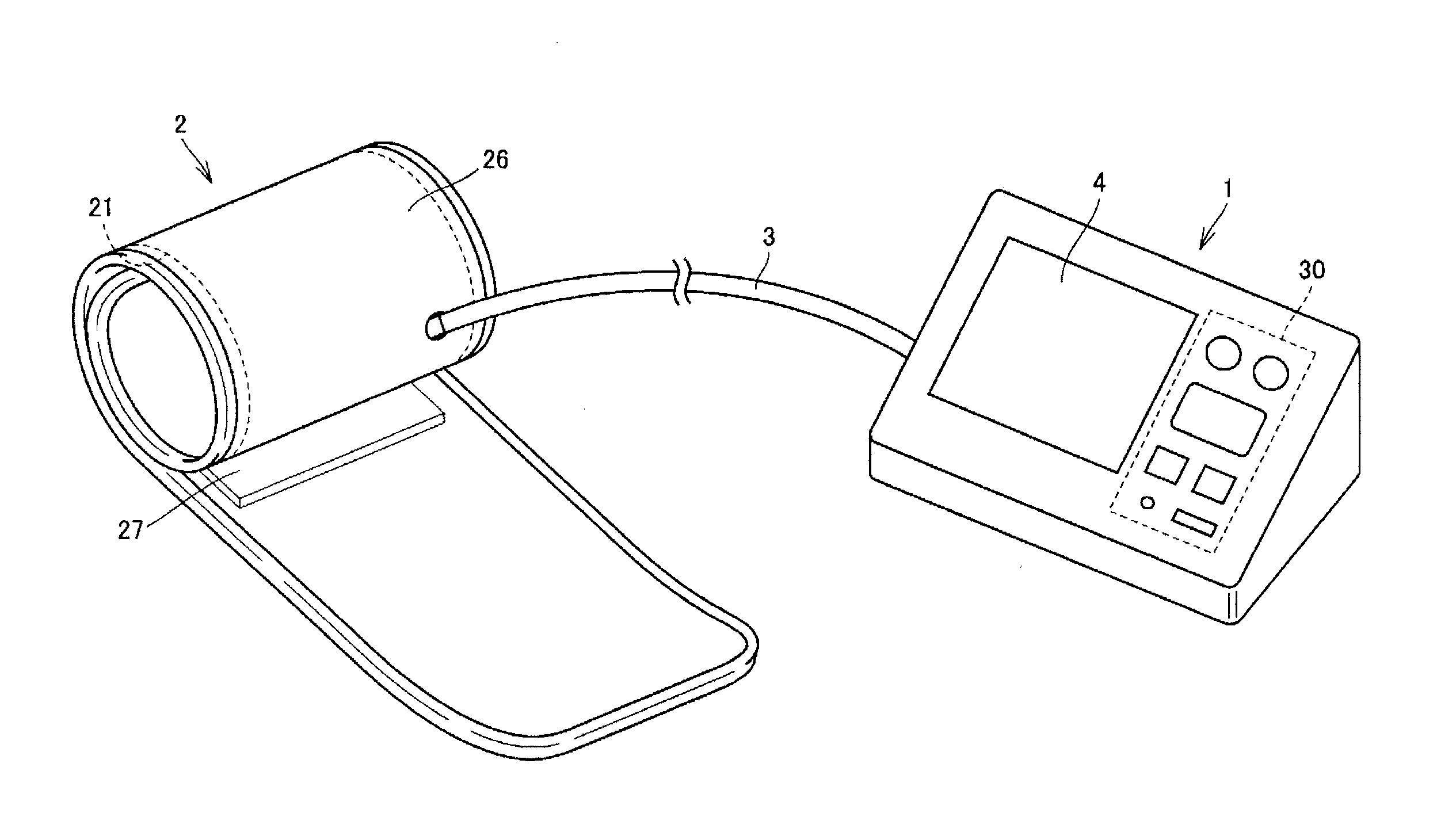
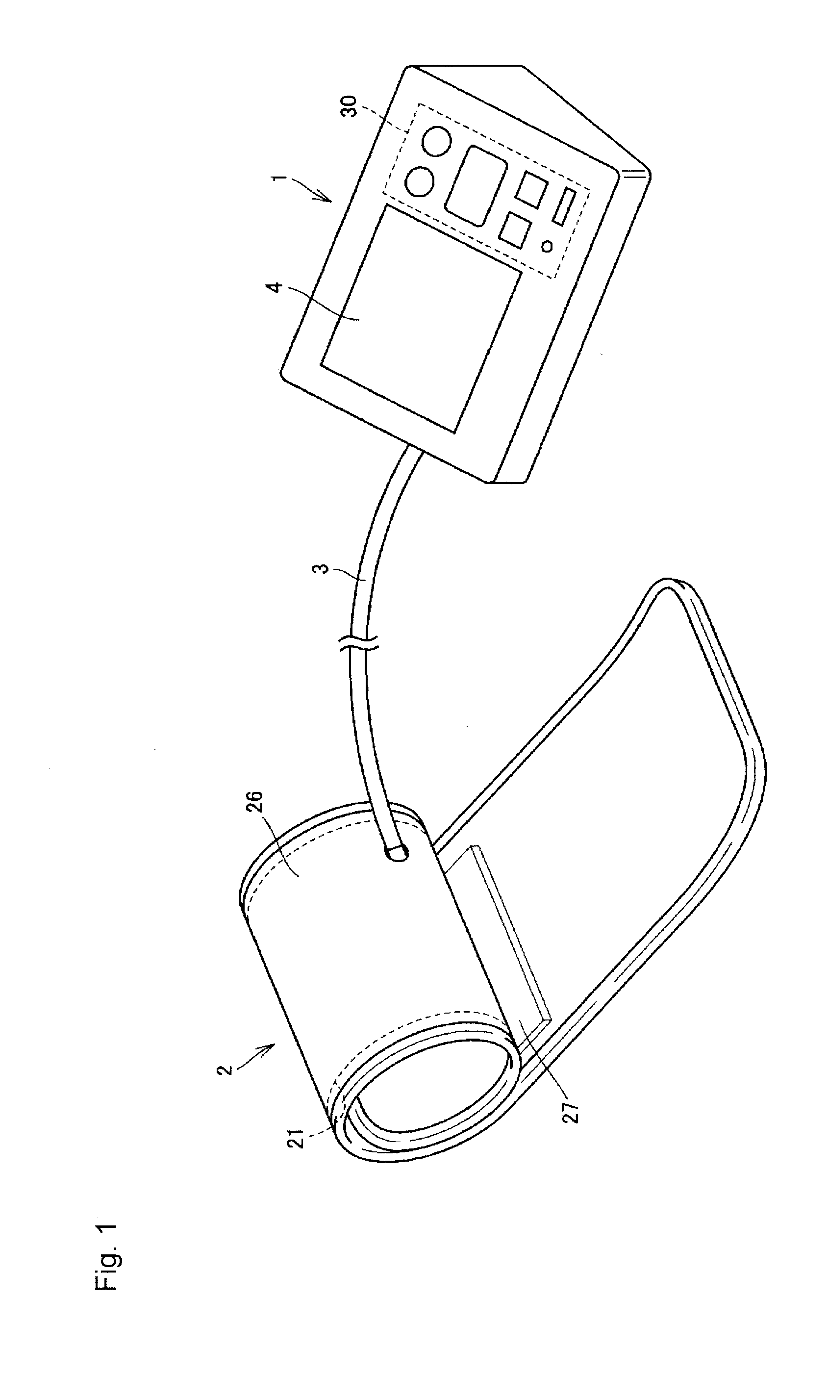
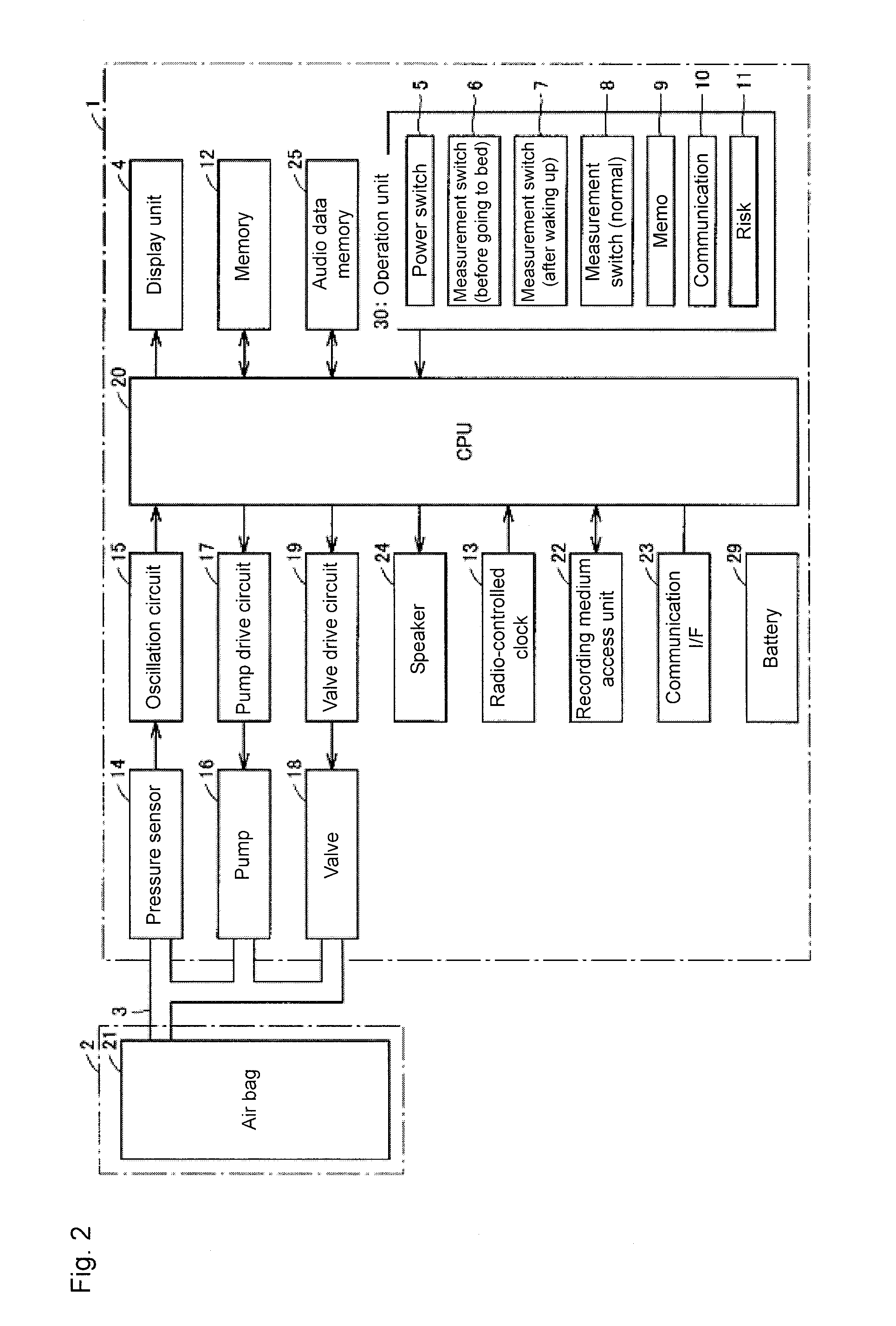
[0038]FIG. 1 is an overall perspective view showing an outer appearance of a blood pressure measurement device. FIG. 2 is a block diagram showing an outline of an internal configuration of the blood pressure measurement device. A schematic configuration of a home use blood pressure measurement device (hereinafter also simply referred to as a sphygmomanometer) will be described with reference to FIG. 1 and FIG. 2. The sphygmomanometer according to one or more embodiments of the present invention includes a main body 1 incorporating a control device for the blood pressure measurement, a cuff 2 to be attached to a blood pressure measurement site of a person to be measured to pressurize a blood pressure measurement site by air pressure, and an air tube 3 for coupling the main body 1 and the cuff 2.

[0039]As shown in FIG. 1, the main body 1 includes on an outer surface a display unit 4 arranged so that the person to be measured can check the display content, and an operation unit 30 arran...

second embodiment

[0073]FIG. 10 is a perspective view showing an arrangement of each device mounted in a main body of a sphygmomanometer according to a second embodiment. FIG. 11 is a side view of each device shown in FIG. 10 when seen from the direction of the arrow XI in FIG. 10. In the second embodiment, the arrangement of the valve 18 with respect to the substrates 41, 42 in the main body 1 of the sphygmomanometer is specified in place of the pump 16 described in the first embodiment.

[0074]FIG. 12 is a cross-sectional schematic view showing the schematic configuration of the valve. As shown in FIG. 12, the valve 18 is a flow rate control valve used to control the gas flow rate discharged from the air bag 21 of the cuff 2 in the sphygmomanometer and gradually lower the pressure in the air bag 21. The flow rate control valve is an electromagnetic drive valve that uses two permanent magnets 205a, 205b and three electromagnetic coils 206a, 206b, 206c, where a housing is configured at the back part of...

third embodiment

[0086]FIG. 15 is a perspective view showing an arrangement of each device mounted in a main body of a sphygmomanometer according to a third embodiment. FIG. 16 is a side view of each device shown in FIG. 15 when seen from the direction of the arrow XVI in FIG. 15. In the third embodiment, the arrangement of the valve 18 with respect to the substrates 41, 42 in the main body 1 of the sphygmomanometer is specified in addition to the arrangement of each device described in the first embodiment.

[0087]As shown in FIG. 15 and FIG. 16, the valve 18 is arranged with the substrate 42 serving as a second substrate interposed with respect to the antenna 31. The substrate 42 is interposed between the valve 18 and the antenna 31. The valve 18 is installed on the lower side of the substrate 42. The valve 18 is arranged to face the antenna non-mounting surface 42b on the side opposite to the antenna mounting surface 42a of the substrate 42. The valve 18 is arranged so that the center line CL3 of t...


PUM


Abstract

A blood pressure measurement device is mounted with a radio-controlled clock function in a main body without lowering reception performance of the standard radio wave of the radio-controlled clock. A substrate including a sensor mounting surface and a sensor non-mounting surface is mounted with a pressure sensor. An antenna for receiving the standard radio wave including time information of the radio-controlled clock is mounted. The antenna includes a bar-shaped magnetic body core and a coil wound around the magnetic body core. A pump is arranged such that an axis line direction of the motor and an extending direction of the magnetic body core are substantially orthogonal. The substrate and the substrate are arranged so that the sensor non-mounting surface of the substrate and the antenna mounting surface of the sensor face each other.

Description

TECHNICAL FIELD[0001]The present invention relates to blood pressure measurement devices, and in particular, to a blood pressure measurement device mounted with a radio-controlled clock.BACKGROUND ART[0002]Recently, the use of a blood pressure measurement device in homes and the like is widely spreading for the purpose of early detection of lifestyle related diseases caused by high blood pressure and blood pressure management. The blood pressure is one index for analyzing the heart function, where performing risk analysis based on the blood pressure is effective in preventing cerebrovascular diseases such as brain hemorrhage and brain infarct, and vascular diseases such as cardio arrest and cardio infarct.[0003]The blood pressure changes by reaction to individual body activity and stress, as well as the cardiovascular back action to a behavior pattern, where the blood pressure has a daily fluctuation rhythm of lowering during sleep and rising before and after waking. For example, th...

Claims


Application Information

Patent Timeline
Patent Type & Authority Patents(United States)
IPC IPC(8): A61B5/02A61B5/022G04B47/06G04G5/00G04G21/04G04G99/00G04R20/08G04R60/10
CPCG04R60/00A61B5/022G04R60/10G04R20/08G04G21/025G04G5/002
Inventor KISHIMOTO, HIROSHITAMAKI, YUUICHIRO
Owner OMRON HEALTHCARE CO LTD
Why Eureka
Try Eureka